321144
63
10.1.5 Diagnostic Modes
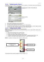
To enter diagnostic modes, press and hold the
MENU
button, then press the
UP
button for 4 seconds. The
PC sensor temperature will be displayed on the LCD as shown in Diagram A. The actual temperature of the
PC is shown.
NOTE 1:
All temperatures shown on display are in degrees Celsius.
NOTE 2:
The door alarms do not operate when the appliance is in diagnostic mode.
PC Sensor Temperature
NOTE:
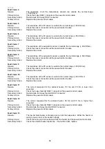
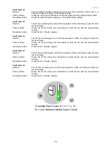
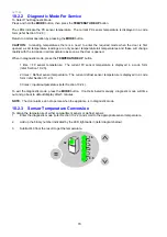
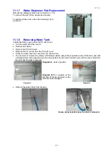
4.0 shown on display, indicates the temperature of the PC sensor is 4.0
O
C (39.2
O
F).
Diagram A
PC Sensor Temperature
FC Sensor Temperature
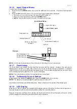
Press the
UP
button once more – FC sensor temperature.
NOTE:
12.0 min shown indicates the temperature of the FC sensor is -12
O
C (10.4
O
F).
Diagram B
FC Sensor Temperature
Defrost Sensor Temperature
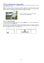
Press the
UP
button once more – Defrost sensor temperature.
NOTE:
18.0 min shown indicates the temperature of the Defrost sensor is -18
O
C (0.4
O
F).
Diagram C
Defrost Sensor Temperature
Summary of Contents for 635 Active Smart
Page 1: ...321144 Service Manual 635 680 790 900 Active Smart Refrigerator Freezer R134a R600a Systems...
Page 2: ...321144 2...
Page 96: ...321144 96 Photo 12 22 5...
Page 100: ...321144 100 Diagram 12 25...
Page 108: ...321144 108 13 11 Embraco Compressor Fitted With External Overload Diagram 13 11...
Page 114: ...321144 114 14 2 Non Ice Water Models Wiring Diagram...
Page 116: ...321144 116 14 4 Ice Water Models Wiring Diagram...
Page 117: ...321144 117 14 5 900 Models Power Control Module Wiring Connections Reciprocating Compressor...
Page 118: ...321144 118 14 6 900 Models Wiring Diagram Reciprocating Compressor...
Page 119: ...321144 119 14 7 900 Models Power Control Module Wiring Connections VC Compressor...
Page 120: ...321144 120 14 8 900 Models Wiring Diagram VC Compressor...
Page 121: ...321144 121 14 9 B Model Wiring Route Diagram 14 9...
Page 122: ...321144 122 14 10 T Model Wiring Route Diagram 14 10...
Page 145: ......

