321144
65
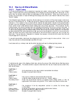
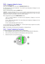
10.1.6 Input / Output Status
To enter input / output status:
•
Press and hold the
MENU
button, then press the
UP
button for 4 seconds. This enters the Diagnostic
mode.
•
Press the
UP
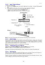
button three times. The current input /output status will be displayed.
•
If a device is on or a door is open, the respective LCD will be on.
•
Return to normal operation by pressing the
MENU
button.
•
NOTE:
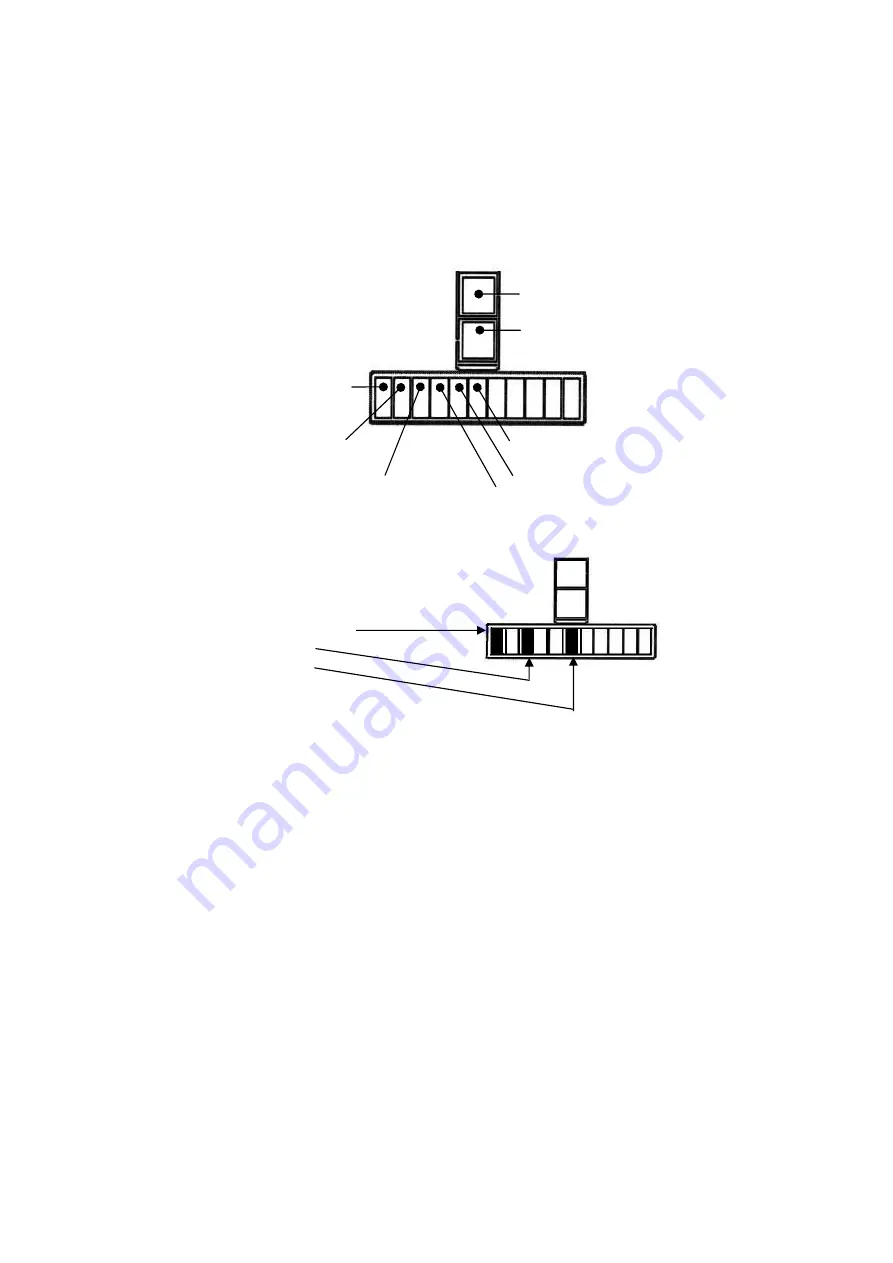
Only the first 6 LCD’s are used. The last 5 are not used.
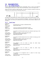
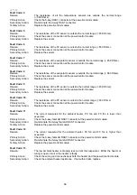
Input/Output Status
Example.
The Compressor is on.
The FC fan is on.
The PC fan is on.
NOTE:
In I/O mode the illumination of the LCD will turn off if either PC doors are opened.
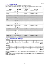
10.1.7 Fault History
The Fault History will indicate the last fault that occurred with the product. However, this will only be
displayed for a periods of 4 days, after which it can only be accessed through a download. It will also
indicate if there are any further faults with the display board. If an icemaker display fault has occurred, these
will be indicated by fault codes F40 or F41 on the LCD Display.
NOTE:
This is fault history and may not necessarily be a current fault.
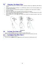
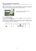
10.1.8 To Manually Force A Defrost
While pressing and holding the
MENU
button, press the
DOWN
button for 4 seconds.
NOTE:
The defrost cycle will not
start
if the defrost sensor is above +8
O
C.
The
defrost cycle follows a predefined sequence. Refer to Section 4.3 for details of the defrost cycle.
10.1.9 LCD Display
When the PC door is opened, the backlight of the display will turn off and the functions will not operate i.e.:
the water dispenser will not work and temperature setting etc. cannot be altered.
However, if the door is left open for 5 minutes, the interior light will turn off and the alarm will sound. At this
point the display will start working and all functions will be operative.
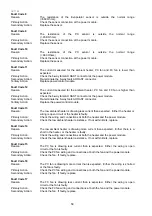
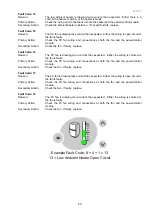
Light on.
Low Ambient heater on.
Defrost heater on.
FC fan on when door
is closed.
Compressor on.
PC Fan on.
Upper door open.
Lower drawer open
Summary of Contents for 635 Active Smart
Page 1: ...321144 Service Manual 635 680 790 900 Active Smart Refrigerator Freezer R134a R600a Systems...
Page 2: ...321144 2...
Page 96: ...321144 96 Photo 12 22 5...
Page 100: ...321144 100 Diagram 12 25...
Page 108: ...321144 108 13 11 Embraco Compressor Fitted With External Overload Diagram 13 11...
Page 114: ...321144 114 14 2 Non Ice Water Models Wiring Diagram...
Page 116: ...321144 116 14 4 Ice Water Models Wiring Diagram...
Page 117: ...321144 117 14 5 900 Models Power Control Module Wiring Connections Reciprocating Compressor...
Page 118: ...321144 118 14 6 900 Models Wiring Diagram Reciprocating Compressor...
Page 119: ...321144 119 14 7 900 Models Power Control Module Wiring Connections VC Compressor...
Page 120: ...321144 120 14 8 900 Models Wiring Diagram VC Compressor...
Page 121: ...321144 121 14 9 B Model Wiring Route Diagram 14 9...
Page 122: ...321144 122 14 10 T Model Wiring Route Diagram 14 10...
Page 145: ......

