321144
67
10.2 Non-Ice & Water Models
10.2.1 Fault Codes
If a fault should develop in the temperature measurement system, defrost system, fans or low ambient
heater, a fault code will be shown automatically on the display and the fault audio alarm will sound. At the
same time, the bottom LED will flash red alternately with the fault LED(s). When any control button is
pressed, the audio alarm is turned off although the display will continue to be “flashed” instead of the normal
“back-lit” display.
The refrigerator goes through a sequence of tests whenever it is turned on at the power supply or whenever
the door is closed while it is on. It takes 20 seconds to complete the test sequence, and opening a door will
interrupt it. If, for example, there is a fault with the fans/low ambient heater connector at the power/control
module (it may be unplugged), and a door is opened as soon as the fault audio alarm sounds, the fault code
shown will be code 13 (low ambient heater drawing less current than expected). This is because the low
ambient heater is the first item tested and so the refrigerator will fault for this but carry on with more tests. If
the doors are left closed until the tests are completed (after 20 seconds), the fault code shown will be code
11 (the current measured for the ambient heater, PC fan and FC fan is lower than expected). It is therefore
recommended that if the fault audio alarm sounds as soon as the refrigerator is turned on, or as soon as the
doors are closed, the service technician should wait for 20 seconds before opening the door to check the
fault code. This will allow the refrigerator to complete the sequence of tests and will ensure that the fault
code displayed is the correct one.
To reset the audio alarm, disconnect the refrigerator from the power supply for a few seconds. If this is not
done, the audio alarm will automatically reset after 72 hours.
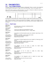
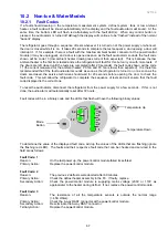
Fault codes will be in a binary code and the LEDs that flash will have the following binary values:
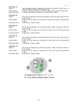
To determine the value of the displayed fault code, add up the values of the LEDs that are flashing (ignore
the flashing red LED). The faults and their respective fault code that can be checked and serviced in the
field are as follows:
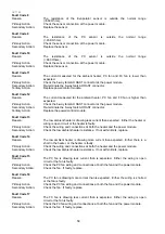
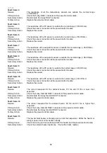
Fault Code: 1
Reason:
On the last power up, the power/control module failed its self-test.
Primary Action:
Replace the power/control module.
Fault Code: 2
Reason:
The previous 2 defrosts were aborted after 60 minutes.
Primary Action:
Check the defrost heater assembly in the FC. If faulty, replace.
Secondary Action:
Check the power/control module is supplying mains voltage (230V or 110V as
appropriate) to the heater during defrost. If not, replace the power/control module.
Fault Code: 3
Reason:
The resistance of all the temperature sensors is outside the normal range
(> 45K Ohms).
Primary Action:
Check the 6-way RAST connector at the power/control module.
Secondary Action:
Re-terminate the 6-way RAST connector.
Tertiary Action:
Replace the power/control module.
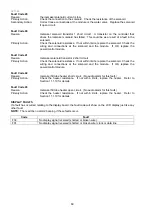
Mode
Button
Temperature Down
Temperature Up
1
2
4
8
16
32
64
12
Summary of Contents for 635 Active Smart
Page 1: ...321144 Service Manual 635 680 790 900 Active Smart Refrigerator Freezer R134a R600a Systems...
Page 2: ...321144 2...
Page 96: ...321144 96 Photo 12 22 5...
Page 100: ...321144 100 Diagram 12 25...
Page 108: ...321144 108 13 11 Embraco Compressor Fitted With External Overload Diagram 13 11...
Page 114: ...321144 114 14 2 Non Ice Water Models Wiring Diagram...
Page 116: ...321144 116 14 4 Ice Water Models Wiring Diagram...
Page 117: ...321144 117 14 5 900 Models Power Control Module Wiring Connections Reciprocating Compressor...
Page 118: ...321144 118 14 6 900 Models Wiring Diagram Reciprocating Compressor...
Page 119: ...321144 119 14 7 900 Models Power Control Module Wiring Connections VC Compressor...
Page 120: ...321144 120 14 8 900 Models Wiring Diagram VC Compressor...
Page 121: ...321144 121 14 9 B Model Wiring Route Diagram 14 9...
Page 122: ...321144 122 14 10 T Model Wiring Route Diagram 14 10...
Page 145: ......


