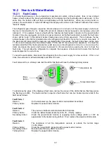
321144
70
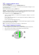
10.2.2 Diagnostic Mode For Service
To Select The Diagnostic Mode:
Press and hold the
MODE
button, then press the
TEMPERATURE
UP
button.
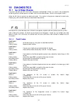
The LEDs indicate the PC sensor temperature. The current PC sensor temperature is displayed in a code
form (refer Section 10.2.3).
Return to normal operation by pressing the
MODE
button.
CAUTION:
In reading temperatures there is a need to enter the required mode when the door is first
opened, as all temperature readings are only sensor temperature/air temperatures and these will change
rapidly with the increase in air temperature as soon as the door is opened.
When in diagnostic mode, press the
TEMPERATURE
UP
button.
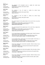
1 time = FC sensor temperature. The current FC sensor temperature is displayed in a code form
(refer Section 10.2.3).
2 times = Defrost sensor temperature. The current defrost sensor temperature is displayed in a code
form (refer Section 10.2.3).
3 times = Inputs/outputs status (refer Section 10.2.4).
To exit the diagnostic mode, press the
MODE
button. If not terminated manually, diagnostic mode will time
out and go back to default display after 5 minutes.
NOTE:
The door alarms do not operate when the appliance is in diagnostic mode.
10.2.3 Sensor Temperature Conversion
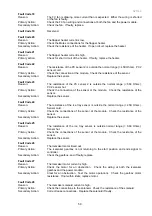
To obtain the temperature of either compartment sensor or defrost sensor:
1.
Enter the diagnostic mode (refer Section 10.2.2) and scroll to the appropriate sensor temperature.
2.
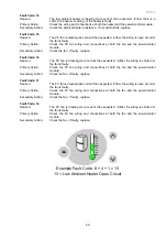
Add up the binary number indicated by the LED light pattern (refer diagram below).
3.
Subtract 40 from the result to get the temperature.
0.5
1
2
4
8
16
32
Summary of Contents for 635 Active Smart
Page 1: ...321144 Service Manual 635 680 790 900 Active Smart Refrigerator Freezer R134a R600a Systems...
Page 2: ...321144 2...
Page 96: ...321144 96 Photo 12 22 5...
Page 100: ...321144 100 Diagram 12 25...
Page 108: ...321144 108 13 11 Embraco Compressor Fitted With External Overload Diagram 13 11...
Page 114: ...321144 114 14 2 Non Ice Water Models Wiring Diagram...
Page 116: ...321144 116 14 4 Ice Water Models Wiring Diagram...
Page 117: ...321144 117 14 5 900 Models Power Control Module Wiring Connections Reciprocating Compressor...
Page 118: ...321144 118 14 6 900 Models Wiring Diagram Reciprocating Compressor...
Page 119: ...321144 119 14 7 900 Models Power Control Module Wiring Connections VC Compressor...
Page 120: ...321144 120 14 8 900 Models Wiring Diagram VC Compressor...
Page 121: ...321144 121 14 9 B Model Wiring Route Diagram 14 9...
Page 122: ...321144 122 14 10 T Model Wiring Route Diagram 14 10...
Page 145: ......

