321144
94
12.18 Replacement Of Low Ambient Heater - “T” Model
1. Disconnect the refrigerator from the power supply.
2. Remove all PC shelving.
3. Remove the bottom PC air duct cover.
4. Remove the polystyrene duct cover insulation.
5. Disconnect the low ambient heater.
6. Refit in reverse manner.
12.19 Replacement Of Low Ambient Heater - “B” Models
This element is mounted in the floor of the divider and is not replaceable. If it should be found to be open
circuit, a replacement low ambient heater can be fitted to the air duct cover.
Should a failure occur, replace the heater with the following part: -
•
Part Number: 883371 – Low Ambient Heater
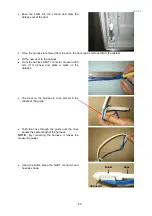
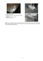
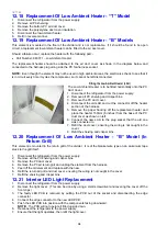
The replacement heater should be attached to the air duct cover as shown in the diagram below and
connected to the harness plug along side the PC fan harness socket.
NOTE:
Even though the element may not be used in high ambient areas, the electronics check to see that it
is in circuit every time it cycles the compressor, so it cannot be left disconnected.
Fitting the Low Ambient Heater (LAH)
The Low Ambient Heater is to be fitted horizontally onto the PC
Duct Cover.
1. Disconnect the refrigerator from the power supply.
2. Remove all PC shelving and crisper bins.
3. Remove the PC duct cover.
4. Disconnect the old LAH and cut the connector off the heater
section of the harness.
5. Remove the paper backing off the replacement heater and
place the heater 150mm (6 inches) from the base of the PC
duct cover as shown on left.
6. Connect the new LAH to the plug socket that the old one
was connected to.
7. Refit the duct cover; ensuring the wiring is not caught in the
cover.
8. Refit the shelving and crisper bins.
12.20 Replacement Of Low Ambient Heater - “B” Model (In
Return Grill)
This element is mounted in the return grill of the divider. It is of the blanket wire type on an aluminium tape
stuck to the grill itself.
1. Disconnect the refrigerator from the power supply.
2. Remove all the PC shelving and crisper bins.
3. Remove the PC duct cover.
4. Remove the PC air return grill and unplug the element from the harness.
5. Peel off the old element and replace with the new.
6. Refit the return air grill and duct cover, ensuring the wiring is not caught in the cover.
7. Refit the shelving and crisper bins.
12.21 Interior LED Light Replacement
1. Disconnect the refrigerator from the power supply.
2. Remove the light cover. (This can be done by using a small screwdriver and levering the cover off the
front clips.)
3. The faulty LED PCB is removed by pulling the PCB out of the socket and disconnecting the edge
connector.
4. Connect the edge connector to the new LED PCB.
5. Push the LED PCB into position with the components facing downward.
NOTE:
The PCB will not operate if fitted upside down.
6. Reconnect the refrigerator to the power supply.
7. Ensure that the light operates, then refit the light cover.
Summary of Contents for 635 Active Smart
Page 1: ...321144 Service Manual 635 680 790 900 Active Smart Refrigerator Freezer R134a R600a Systems...
Page 2: ...321144 2...
Page 96: ...321144 96 Photo 12 22 5...
Page 100: ...321144 100 Diagram 12 25...
Page 108: ...321144 108 13 11 Embraco Compressor Fitted With External Overload Diagram 13 11...
Page 114: ...321144 114 14 2 Non Ice Water Models Wiring Diagram...
Page 116: ...321144 116 14 4 Ice Water Models Wiring Diagram...
Page 117: ...321144 117 14 5 900 Models Power Control Module Wiring Connections Reciprocating Compressor...
Page 118: ...321144 118 14 6 900 Models Wiring Diagram Reciprocating Compressor...
Page 119: ...321144 119 14 7 900 Models Power Control Module Wiring Connections VC Compressor...
Page 120: ...321144 120 14 8 900 Models Wiring Diagram VC Compressor...
Page 121: ...321144 121 14 9 B Model Wiring Route Diagram 14 9...
Page 122: ...321144 122 14 10 T Model Wiring Route Diagram 14 10...
Page 145: ......

