background image

FISHERPAYKEL.COM

© Fisher & Paykel Appliances 2019. All rights reserved.

The appliance specifications in this document apply to the specific 
appliances and models described at the date of issue. Under our policy 
of continuous appliance improvement, these specifications may change 
at any time. You should therefore check with your Dealer to ensure this 

booklet correctly describes the appliance currently available.

Complete and keep for safe reference:

Model 

 ____________________________________________________________

Serial No. 

 ____________________________________________________________

Purchase Date 

 ____________________________________________________________

Purchaser 

 ____________________________________________________________

Dealer Address  

 ____________________________________________________________

Installer’s Name 

 ____________________________________________________________

Installer’s Signature 

 ____________________________________________________________

Installation Company   ____________________________________________________________

Installation Date 

 ____________________________________________________________


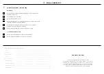
TO BE COMPLETED BY THE INSTALLER

All models


 Ensure all internal and external packaging is removed from the 
appliance before use.


Check all parts are installed.


 Ensure the appliance is level.


 Ensure the appliance is securely fastened to the cabinetry with the 
supplied anti-tip bracket and fittings.


 Ensure the doors / drawer can open and close freely with no 
resistance from surrounding cabinetry.


 Ensure hinge limiting pin is fitted for 90

°


door swing.

Ice and Water models only


 Ensure the water filtration system has been flushed.


 Ensure a manual ice maker cycle has been forced.

@4

 FINAL CHECKLIST

Summary of Contents for ACTIVESMART RS80

Page 1: ...ACTIVESMART INTEGRATED FRENCH DOOR REFRIGERATOR FREEZER RS80 and RS90 models INSTALLATION GUIDE NZ AU GB IE HK SG IN 862068A 06 19 ...

Page 2: ......

Page 3: ...rrent details about model and specification availability in your country go to our website fisherpaykel com or contact your local Fisher Paykel dealer CONTENTS 1 SAFETY AND WARNINGS 2 COMPONENTS 3 TOOLS 4 APPLIANCE AND CAVITY DIMENSIONS 5 CABINETRY OPTIONS 7 CUSTOM DOOR PANEL INSTALLATION DIMENSIONS 8 CUSTOM DOOR PANEL INSTALLATION TEMPLATE 9 DOOR CLEARANCE 0 ELECTRICAL AND PLUMBING 1 BEFORE INSTA...

Page 4: ......

Page 5: ...ose of ice and refer to the flushing instructions detailed in the installation section of this user guide installation guide If unpleasant taste or odor persists you may wish to fit a new filter cartridge Use new tubing supplied with the appliance DO NOT reuse old tubing from old water and ice connections Your water filtration system can withstand up to 120psi 827kPa of water pressure Ensure the s...

Page 6: ...t Dual adhesive tabs 6 per each strip 12 Side cover 4 Top cover 2 X Install fasteners kit 8 x 16 Mush Washer Twin Thread Philips Screw 8 x 16 Mush Washer Twin Thread Philips Screw M5x10 cross head screw 10 8Gx16 flat head screw 2 Not used for this model 8 x 19 Countersunk Twin Thread Posi Screw 8Gx19 twin thread screw 2 12x12 Countersunk screw 2 Not used for this model Y Miscellaneous components H...

Page 7: ...E GARANZIA SERVICE GARANTIE HUOLTO JA TAKUU SERVICE OG GARANTI 保 修 和 维 修 服務和保修 ACTIVESMART INTEGRATED SLIDE IN REFRIGERATOR RS90 RS90AU models INSTALLATION GUIDE NZ AU GB IE HK SG IN 844219B 02 19 User guide 1 Service and Warranty 1 Installation guide 1 Collet locking clip 1 Water filter 1 Filter cartridge tool 1 Toe kick filter 1 Water tap adaptor 1 Ice and Water display Ice and Water models only...

Page 8: ... Head SS Philips Screw M5 x 14 Mush Head SS Philips Screw M5x14 mush cross head SS screw 34 M5x14 mush cross head SS screw 34 Door handle kit Not supplied and must be purchased separately Select between the options below Contemporary round door handle 3x Contemporary square door handle 3x M5 x 25 Pan Head Socket Screw M5 x 25 Pan Head Socket Screw M5x25 pan head socket screw 12x M5x25 pan head soc...

Page 9: ...804 900 904 H Overall depth of cavity 650 650 I Minimum cabinetry gap clearance from edge of appliance 4 4 J Minimum required finished return 89 89 When adjoining cabinetry cannot share 4mm door gap Total front panel width with required gaps at sides 804mm For flush cabinetry where gap cannot be shared between appliance and adjoining cabinet make cavity width 804mm for RS80 and 904mm for RS90 door...

Page 10: ...iance with the cabinetry Proud installation Flush installation Note Drawings are only for reference and not the actual cavity width of the cabinetry FRAMED CABINETRY Aligns the appliance with the frame of the cabinetry 5 CABINETRY OPTIONS ...

Page 11: ... 598 E Height from bottom of appliance to top of drawer panel 698 698 F Width of bottom drawer panel 796 896 G Gap between top door panels and bottom drawer panel 4 4 H Depth of door and drawer panels excluding handle 18 18 i Height of toe kick from bottom of drawer to floor 100 100 Maximum weight of each top door panel with handle 10kg 10kg Maximum weight of bottom drawer panel with handle 11kg 1...

Page 12: ...ket attachment Do not penetrate front surface 342 3mm TOP PANEL REAR VIEW All measurements to be made from inner bottom corner For the second panel mirror and repeat dimensions using inner bottom corner as the reference point Ø2mm REF 10x Pilot holes recommended for bracket attachment Do not penetrate front surface 335mm 111 5mm 29 1mm 87 2mm 492mm 542mm 366mm All measurements to be made from top ...

Page 13: ...cket attachment Do not penetrate front surface 392 3mm TOP PANEL REAR VIEW All measurements to be made from inner bottom corner For the second panel mirror and repeat dimensions using inner bottom corner as the reference point Ø2mm REF 10x Pilot holes recommended for bracket attachment Do not penetrate front surface 385mm 128mm 29 1mm 87 2mm 492mm 542mm 416mm All measurements to be made from top a...

Page 14: ...LH DOOR PANEL HINGE SIDE SIDE BRACKET HOLES SIDE BRACKET HOLES PRINT SPECIFICATION REVISIONS DRWN DATE CHKD ECN REV BJ 04 04 19 1 1 862946 GRAPHICS RS90 DOOR TEMPLATE TITLE DRAWN DATE SCALE 1 1 FISHER PAYKEL APPLIANCES LIMITED GRAPHICS NO REVISION BINIL JOSE 04 04 2019 400mm LH DOOR PANEL HINGE SIDE LH DOOR PANEL HANDLE SIDE HANGING BRACKET HOLES HANGING BRACKET HOLES FLIP FOR RIGHT HAND DOOR PANE...

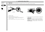
Page 15: ...g handle 360 360 D Minimum door clearance to adjacent wall 115 full internal access 280 300 E Minimum door clearance to adjacent wall 90 reduced internal access 100 100 Measured from front cabinetry edge includes 2mm cabinetry gap Insert hinge limiting pin WARNING Before opening the doors ensure that the appliance is stable Follow these steps to avoid risks that can cause serious injury or death F...

Page 16: ...Electrical and water connections must be within this space if located behind the appliance and must not protrude from the back wall RS80 RS90 ELECTRICAL AND PLUMBING DIMENSIONS mm mm A Overall height of supply area 130 130 B Overall width of supply area 275 355 C Distance from left side of cavity 145 145 D Distance from the floor 72 72 Note Dimensions are based on minimum depth of cavity Do not lo...

Page 17: ...lug 800mm Applicable to Ice and Water models only RS80 RS90 ELECTRICAL SPECIFICATIONS Supply 230V 50 Hz 230V 50 Hz Service 10 amp circuit 10 amp circuit RS80 RS90 PLUMBING SPECIFICATIONS Supply 13mm 1 2 or 19mm 3 4 BSP threaded water connection 6 35mm LLDPE tubing 13mm 1 2 or 19mm 3 4 BSP threaded water connection 6 35mm LLDPE tubing Service Minimum 22 psi 150 kPa Maximum 120 psi 827 kPa 20 C Mini...

Page 18: ...ave dislodged from the rear of the appliance during transit USER GUIDE NZ AU GB IE HK SG IN US ACTIVESMART INTEGRATED REFRIGERATOR RS90A RS9120W RS36A72 RS36A80 RS36W80 models Water fittings and Water filter kits Installation kit 2 Remove the water fittings and water filter kits Installation kit and Miscellaneous items pack from inside the appliance Refer to Components pages 4 5 IMPORTANT Be caref...

Page 19: ...inished return of solid material is required across the top and sides of the new or existing alcove Refer to the Appliance and cavity Dimensions page 7 prior to installation of the appliance 2 Check the power supply Ensure that there is a separate power outlet for the appliance Avoid sharing the power point with other appliances to prevent the appliance from accidentally switching off For power re...

Page 20: ...acket If the minimum 60mm overlap cannot be achieved install a solid spacer to the wall stud behind the bracket IMPORTANT When positioning the appliance in the cabinetry ensure that the anti tip bracket overlaps the appliance by a minimum 60mm for a secure hold 60mm overlap Anti tip bracket 60mm overlap Spacer Anti tip bracket D E B C Anti tip bracket A 1 Project horizontally from the bottom edge ...

Page 21: ...nd Water models only Water tap adaptor 1 Collet locking clip 1 3 WATER SUPPLY CONNECTION 3 Secure connection by inserting a locking key D between the water tap adaptor and locking collet 4 Connect the water tap adaptor to a water tap E Flush water through the hose prior to connection to the appliance to remove any debris in the hose 5 Turn on the water tap and check all connection are dry and free...

Page 22: ...ply D and turn on the appliance 3 Attach the power cord clip to the back of your appliance and secure the excess power cord length onto the clip E When pushing the appliance into position take care not to roll over or damage the power cord and or water tubing Refer to Electrical and Plumbing for more information on recommended and alternative water and power connections DETAIL B SCALE 1 5 B D C 2 ...

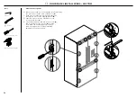
Page 23: ...doors carefully 4 Loosely screw 1 2 turns M5x10 cross head screws into doors D Repeat this process for all appliance doors 1 2 turns D B 1 8 L O A C 2 Remove the left hinge end cap Hold onto the corner of the end cap firmly push to the right to disengage the securing hook and pull down A Pull cap gently towards the left hinge to remove B Keep the end hinge cap for later installation 3 Remove the r...

Page 24: ...nti tip bracket overlaps the appliance by a minimum 60mm for a secure hold B A IMPORTANT Your appliance is fitted with front and rear rollers designed for moving the appliance in the forwards and backwards direction Avoid moving the appliance in a sideways direction as this may damage the rollers or the floor covering surface Ensure the hose is not run over by the appliance when pushing into the c...

Page 25: ...y Tools Ruler Powered driver optional Cross head screwdriver IMPORTANT Ensure all four corners of the appliance is supported firmly onto the floor to eliminate any movement DO NOT install the appliance on a soft uneven or unlevelled floor to avoid twisting the appliance and poor door sealing We recommend to use A 4mm hex key One turn of height adjusting nuts is equivalent to 1mm height adjustment ...

Page 26: ...panels 4 Remove the plastic plugs from the handle holes 4 per each door panel 5 Align the handle holes with the door panel holes and secure with M5x25 pan head socket screws 4 per each door panel Note Door handle kit available and must be purchased separately Refer to Components page 5 for more details A A B B Attach side brackets and straps C 7 Align the brackets and straps to the holes on the si...

Page 27: ...ng firmly until you feel it clip securely D On the external display enable the dispenser lock to prevent any water from dispensing during water connection To lock press the button for 4 seconds The LED above the button will illuminate D B A 5 Remove water tube from the holder on the appliance door C 6 Hang the door panel onto M8 studs Ensure the panel is free to pivot for water connections C 9 Pus...

Page 28: ...e at the sides of the doors A 2 Hang the door panel by inserting the M8 studs through the holes of the hanging bracket B 3 Slide the forks of the side brackets onto the screws of the door C 4 Screw the M8 washer and nut to each stud D and re tighten the side screws E using the hex key and spanner to fix the door panel do not fully tighten This will allow opening the door without affecting adjustme...

Page 29: ...he panel turn the stud clockwise to raise or counter clockwise to lower the door panel A 3 Once satisfied with the alignment secure M8 studs with M8 washer and M8 nut B The top of the stud must remain below the top face of the door panel 4 Secure side bracket forks by tightening side screws C Repeat for all door panels Note For depth adjustment loosen the side screws adjust the panels and then ret...

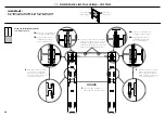
Page 30: ...E BRACKET HOLES DOOR PANEL SIDE BRACKET HOLES DOOR PANEL SIDE BRACKET HOLES DOOR PANEL SIDE BRACKET HOLES DOOR PANEL SIDE BRACKET HOLES DOOR PANEL SIDE BRACKET HOLES FLIP FOR LEFT DOOR PANEL LH DOOR PANEL HINGE SIDE LH DOOR PANEL HANDLE SIDE DRAWER PANEL HANDLE SIDE DRAWER PANEL HINGE SIDE FLIP FOR RIGHT DOOR PANEL LH DOOR PANEL HINGE SIDE LH DOOR PANEL HANDLE SIDE LH DOOR PANEL BOTTOM EDGE RH DOO...

Page 31: ...S DOOR PANEL SIDE BRACKET HOLES DOOR PANEL SIDE BRACKET HOLES DOOR PANEL SIDE BRACKET HOLES DOOR PANEL SIDE BRACKET HOLES DOOR PANEL SIDE BRACKET HOLES DOOR PANEL SIDE BRACKET HOLES FLIP FOR LEFT DOOR PANEL 3 Move the same template to right hand side of door panel 1B Align bottom of template with bottom edge of top door panel 1A Align left side edge of template with left side edge of top door pane...

Page 32: ...EL SIDE BRACKET HOLES DOOR PANEL SIDE BRACKET HOLES DOOR PANEL HANGING BRACKET HOLES DOOR PANEL HANGING BRACKET HOLES DOOR PANEL SIDE BRACKET HOLES DOOR PANEL SIDE BRACKET HOLES FLIP FOR LEFT DOOR PANEL DRAWER PANEL TOP EDGE LH DOOR PANEL HINGE SIDE LH DOOR PANEL HANDLE SIDE DRAWER PANEL HANDLE SIDE DRAWER PANEL HINGE SIDE LH DOOR PANEL HINGE SIDE LH DOOR PANEL HANDLE SIDE DRAWER PANEL HANDLE SIDE...

Page 33: ...e kit available and must be purchased separately Refer to Components page 5 for more details Attach side brackets and straps E 6 Align the brackets and straps to the holes on the side of the panel and secure with 8x16 mush washer screws 20 Attach the hanging brackets D 4 Align the bracket to the holes and secure with 8x16 mush washer screwS 14 C C D D Internal box B Door panel attachment kit Side ...

Page 34: ...ing bracket B 3 Slide the forks of the side brackets onto the screws of the door C 4 Screw the M8 washer and nut to each stud D and re tighten the side screws E to fix the door panel do not fully tighten This will allow opening the door without affecting adjustment of the door panel B D C A E Tools Hex key FPA spanner 1 Cross head screwdriver Powered driver optional 9 DOOR PANEL INSTALLATION CUSTO...

Page 35: ...tud must remain below the top face of the door panel 4 Secure side bracket forks by tightening side screws C Repeat for all door panels Note For depth adjustment loosen the side screws adjust the panels and then retighten once satisfied Further adjustment of door panels can be achieved by removing door panels then loosening the fixing screws for the hanging bracket and moving the bracket sideways ...

Page 36: ...event back and forth movement Reattach the hinge end caps 3 Reattach the left hinge end cap B z z Align hinge cap to the appliance press and firmly slide the cap to the right z z Hold onto the corner of the end cap firmly push up and to the left to engage securing hook Ensure cap is flush with the appliance B C 4 Reattach right hinge end cap C z z Align hinge cap to appliance press and firmly slid...

Page 37: ...ed air in the water tank and filter system Refer to the user guide Operating instructions Automatic ice maker for more information Install the water filter 1 Remove the plastic wrapping of the new filter 2 Pull the freezer drawer out slightly and insert the filter into the casing at the bottom left corner of the appliance Ensure the filter handle is positioned vertically A 3 Push the cartridge fir...

Page 38: ...h until it clips securely A 2 Align the top grille clips to the top plinth slots Ensure the top grille is in the correct orientation B 3 Push the grille firmly onto the appliance until the clips engage C MI Pack Toe kick filter 1 External box Toe kick grille 1 C 2 TOE KICK INSTALLATION ...

Page 39: ...acking on one side only 4 Press firmly to the underside of the drawer top trim in the indicated locations F 5 Remove the remaining adhesive backing from the dual adhesive tabs 6 Locate the trim against the back surface of the panel and press down firmly Ensure the trim is fully seated against the drawer surface G 7 Install the side trims by inserting into the panel gaps on each side of the door s ...

Page 40: ..._______________________________________________ Installer s Name _____________________________________________________________ Installer s Signature _____________________________________________________________ Installation Company _____________________________________________________________ Installation Date _____________________________________________________________ TO BE COMPLETED BY THE INS...

Reviews: