479536
26
4.4
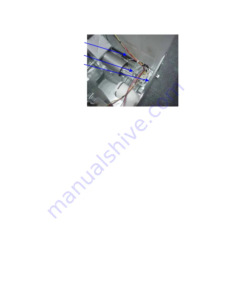
Gas Valve Assembly Replacement
Flame Detect Thermostat
Burner
Gas Valve
•
Disconnect the power and gas supply.
•
Remove the drum assembly.
•
Disconnect the wiring harnesses from the gas coils.
•
Unscrew the bracket for the supply pipe from the back panel.
•
Unscrew the valve bracket and feed the entire gas burner and valve assembly out through the
opening in the front cabinet bracket.
•
Remove the two screws securing the burner to the valve bracket.
•
Remove the two screws securing the valve to the valve bracket.
•
Remove the two screws securing the coils to the valve.
Reassembly is the reverse procedure.
4.4.1
Flame Detect Thermostat Replacement
•
Disconnect the power supply.
•
Remove the drum assembly.
•
Unscrew and remove the burner.
•
Disconnect the wires to the flame thermostat.
•
Undo the 2 screws securing the combustion chamber.
•
Turn the chamber to the left; undo the screws holding the thermostat and remove.
Reassembly is the reverse procedure.
Summary of Contents for DE09
Page 1: ...479536 Service Manual Dryers Models DE09 DG09 DE60FA DG60FA ...
Page 4: ...479536 4 9 3 Electric Selector Sequence 49 9 4 Gas Selector Sequence 50 ...
Page 6: ...479536 6 2 INSTALLATION 2 1 Electric Model Installation ...
Page 7: ...479536 7 ...
Page 8: ...479536 8 ...
Page 9: ...479536 9 ...
Page 10: ...479536 10 ...
Page 11: ...479536 11 2 2 Gas Model Installation ...
Page 12: ...479536 12 ...
Page 13: ...479536 13 ...
Page 14: ...479536 14 ...
Page 15: ...479536 15 ...
Page 16: ...479536 16 ...
Page 19: ...479536 19 4 COMPONENT SERVICING 4 1 Top Disassembly ...
Page 40: ...479536 40 No Heat Fluff Normal Heat Cotton Regular ...
Page 45: ...479536 45 7 FLOW CHARTS 7 1 Electric Flow Chart ...
Page 46: ...479536 46 7 2 Gas Flow Chart ...
Page 47: ...479536 47 8 WIRING DIAGRAMS 8 1 Electric Wiring Diagram ...
Page 48: ...479536 48 8 2 Gas Wiring Diagram ...
Page 50: ...479536 50 9 4 Gas Selector Sequence ...
Page 51: ...479536 51 ...


