background image

Installation instructions

20

Electrical connection information for gas dryers

 WARNING!

Electrical Shock Hazard

Make sure appliance is wired or plugged into a grounded outlet.
Improper connection of the equipment-grounding conductor can result in 

a risk of electric shock. Check with a qualified electrician or service person 

if you are in doubt as to whether the appliance is properly grounded.
Do not modify the plug if it will not fit the outlet.
Have the proper outlet installed by a qualified electrician.
Do not use an adaptor.
Do not use an extension cord.
Failure to follow these instructions can result in death, fire or 

electrical shock.

The appliance must be electrically grounded in accordance with all local codes and ordinances. 
In the absence of local codes, the dryer must be electrically grounded in accordance with the 
National Electrical Code, ANSI/NFPA NO. 70, or the Canadian Electrical Code, CSA C22.1.

Electrical requirements for gas dryers

The power supply must be 120V, 60Hz, and connected to a properly grounded branch circuit, 
which is protected by a 15 or 20 amp circuit breaker, or a time-delay fuse.

If the electrical supply provided does not meet specifications outlined above, the installation of 
an approved outlet by a licensed electrician is recommended.

Important!

The dryer is supplied with a three-prong (grounding) plug for your 
protection against electric shock. The plug should be plugged 
directly into a correctly grounded three prong power socket. 
DO NOT cut or remove the grounding terminal from this plug.

Ensure proper ground exists before use.

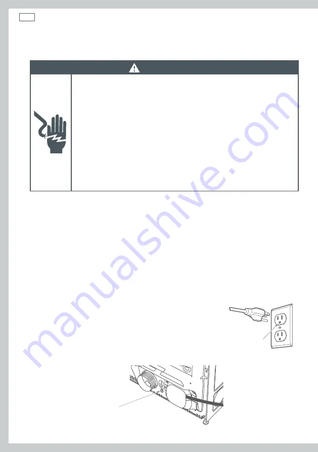
If local codes permit, an external 
ground wire (not provided), which 
meets local codes, may be added by 
attaching to the green ground screw 
on the rear of the dryer, and to a 
grounded metal cold water pipe or 
other established ground.

Fig.13 Grounding screw

Ensure proper 
ground exists 
before use

Summary of Contents for DG7027G1

Page 1: ... Damp dry signal Yes Delay Start Yes Reversible Door Yes Drying progress indicator Yes Time remaining indicator Yes Capacity Cubic feet 7 0 Cycles Dry Cycles 6 Steam cycle No Regular Yes Heavy Yes Delicate Yes Allergy Yes Air Dry Yes Time Dry Yes Dryer exhaust Location 4 Left 2 bottom 1 and rear 1 Warranty Complete 2 years warranty Entire Appliance In Home Parts Labour Powered by TCPDF www tcpdf o...

Page 2: ...carefully These instructions must be left with the home owner for future reference Correct installation is the responsibility of the installer Installation of this appliance must be performed by a qualified installer The dryer must be exhausted to the outdoors Remove the door from an old dryer before it is removed and discarded The wiring diagram and service information can be found in the control...

Page 3: ...tion to the customer s home 1 Remove packaging Remove all of the outer packaging Dispose of unwanted packaging thoughtfully 2 Discard packing material from around dryer feet Tilt the dryer sideways and remove the foam shipping pads by pulling at the sides and breaking them away from the dryer feet Be sure to remove all the foam pieces before continuing with installation 3 Drying rack selected mode...

Page 4: ...not install the dryer in any room or closet which does not permit the free flow of replacement air The free area of any opening for the introduction of outside air shall not be less than twice the area of the dryer exhaust outlet The area in which the dryer is located must be kept clear and free from combustible materials gasoline and other flammable vapors and liquids A dryer produces combustible...

Page 5: ...the dryer for intake air The minimum clearance to combustible surfaces and for air openings are 1 25 mm clearance both sides 2 51 mm clearance at the front and 1 25 mm clearance at the rear or 5 127 mm clearance if the dryer exhaust duct is at the rear Consideration must also be given to provide adequate clearance for proper operation and service 291 2 743 mm 27 683 mm 41 1 2 1051 mm Fig 3 AeroCar...

Page 6: ...minimum of 60 sq in 387 cm2 of open area equally distributed If the closet contains both a washer and a dryer doors must contain a minimum of 120 sq in 774 cm2 of open area equally distributed The openings must never be obstructed a louvered door with the minimum air opening is acceptable Minimum installation clearances are required but more clearance is recommended 1 25 mm 1 25 mm 1 25 mm min 1 2...

Page 7: ...ly fastened to a non combustible portion of the mobile home structure The exhaust MUST NOT be terminated beneath a mobile or manufactured home The exhaust duct material MUST BE METAL The exhaust duct MUST NOT be connected to any other duct vent or chimney or be vented into a wall ceiling or concealed space of a building Do not use sheet metal screws or other fastening devices which extend into the...

Page 8: ...nnector this must not exceed a length of 3 feet in total WARNING Explosion Hazard Installations must be performed by a qualified or licensed contractor plumber or gasfitter qualified or licensed by the state province or region where this appliance is being installed Use a new AGA or CSA approved gas supply line Install a shut off valve in an accessible place Only use a gas shut off valve approved ...

Page 9: ...ryer must be disconnected from the gas supply piping system during any pressure testing of the system at a pressure greater than 0 5 psi 3 5 kPa The dryer must be isolated from the gas supply piping system by closing the equipment shut off valve during any pressure testing of the gas supply piping of test pressure equal to or less than 0 5 psi 3 5 kPa Gas supply A 1 8 National Pipe Taper NPT plugg...

Page 10: ... rate of four percent per 1000 feet 305 m elevation above sea level Installation must conform to all local codes and ordinances In the absence of local codes and or ordinances installation shall conform to the National Fuel Gas Code ANSI Z223 1 NFPA 54 or the Natural Gas and Propane Installation Code CSA B149 1 Gas supply connection Note add to vertical dimension the distance between cabinet botto...

Page 11: ...ressure Shut off valve Pipe size at least 1 2 12 7 mm Connecting to dryer Install a female 3 8 NPT elbow at the gas inlet end of the dryer Attach a 3 8 flare union adapter to the female NPT elbow Using two adjustable wrenches tighten the flexible gas line connection Fig 9 Tighten connections Apply pipe compound to the adapter and dryer gas inlet threads Fig 8 Attaching elbow and adapter Important ...

Page 12: ...s Test for gas leaks WARNING NEVER use an open flame to test for gas leaks Turn on the gas open the gas shut off valve All connections should be checked for leaks with a soapy or equivalent solution Apply a soap or equivalent solution to the connection points If leaks are found close the shut off valve re tighten the joint then repeat the test Note Do not use a solution that contains ammonia This ...

Page 13: ...ing Hazard Gas leaks cannot always be detected by the sense of smell Use of an approved UL or CSA gas detector is recommended If a gas leak is detected follow the What to do if you smell gas instructions stated on the inside font cover of this user guide ...

Page 14: ... National Electrical Code ANSI NFPA NO 70 or the Canadian Electrical Code CSA C22 1 Electrical requirements for gas dryers The power supply must be 120V 60Hz and connected to a properly grounded branch circuit which is protected by a 15 or 20 amp circuit breaker or a time delay fuse If the electrical supply provided does not meet specifications outlined above the installation of an approved outlet...

Page 15: ... an extension cord or adapter plug with the dryer Use only new ducting materials Remove and discard old duct material WARNING Electric Shock Hazard Use a new UL CSA listed 30 ampere power cord Use a UL listed strain relief Disconnect power before making electrical connections Connect neutral wire white or center wire to center terminal On all four wire installations remove the grounding link and c...

Page 16: ...ctrician if the electricity supply does not meet the required specifications Grounding instructions This dryer MUST be connected to a grounded metal permanent wiring system Alternatively an equipment grounding conductor must be run with the circuit conductors and connected to the equipment grounding terminal on the dryer WARNING Improper connection of the equipment grounding conductor can result i...

Page 17: ...cord according to the following a Connect the two hot lines to the outer screws of the terminal block labelled L1 and L2 b Connect the neutral white line to the center of the terminal block labelled N 7 Use the green ground screw to attach the ground wire of the power cord ie relocate the green ground screw to the hole above strain relief bracket 8 Tighten all three terminal block screws completel...

Page 18: ...al white Neutral white Screws 3 Screws 3 Ground strap Green ground screw Fig 15 3 wire connections 1 Turn off the circuit breaker s 30 amp 2 Ensure the dryer cord is unplugged from the wall outlet 3 Locate and remove the power cord cover at the lower rear of the dryer 4 Install a 19 mm UL recognized strain relief to the entry hole for the power cord Move the power cord through the strain relief 5 ...

Page 19: ...circuit breakers The power supply must be a 4 wire single phase 120 240 V 60Hz 30 amp circuit This dryer is supplied with a CSA approved power cord 5 feet 1 52 m in length intended for plugging into a 14 30R wall outlet Ensure the outlet is within reach of the dryer s final location 4 wire NEMA type 14 30R A replacement power cord is available if required Use of part number 248C1014G001 240 V cord...

Page 20: ...attic under an enclosed floor or into any concealed space of a building Never vent the dryer into a common duct with an exhaust system originating from a kitchen The combination of grease and lint creates a potential fire hazard Ducting must be kept as short in length and as straight as possible Ducts can accumulate lint and create a potential fire hazard Do not exceed the maximum exhaust duct len...

Page 21: ...298 mm 3 1 2 89 mm Exhaust outlet Before you start If required remove and discard of all existing plastic or metal foil duct Replace this with UL listed duct material Check for and remove any lint from the vent opening in the wall Ensure the exhaust hood damper moves freely Internal duct opening Wall Check that exhaust hood damper opens and closes freely Fig 17 House vent opening ...

Page 22: ...ight ducting including the distance between the last turn and the wall cap to ensure the best performance of the dryer Turns other than 90 One turn of 45 or less may be ignored Two 45 turns are to be considered equal to one 90 turn Each turn greater than 45 should be considered as equal to one 90 turn Important Choose a route that will provide the straightest and most direct path to the outdoors P...

Page 23: ...ation and lint build up Connecting the dryer to the house vent Rigid metal duct The use of a rigid metal ducting is recommended for best drying performance The risk of crushing and kinking of the duct is reduced when using this duct material UL listed flexible metal semi rigid transition duct If rigid metal duct is not appropriate a UL approved flexible metal semi rigid duct material can be used k...

Page 24: ...all be used in the United States and Canada Do not install flexible metal duct in walls ceilings floors or other enclosed spaces Flexible metal duct shall not exceed 8 feet 2 4 m in total Do not rest the ducting on sharp materials and objects To ensure the best performance of flexible metal semi rigid and foil type transition duct 1 Slide one end of the duct over the exhaust outlet pipe at the bac...

Page 25: ...bend or collapse ducting Use elbows if turns are necessary DO NOT use excessive exhaust length Cut duct as short as possible DO NOT crush duct against the wall DO NOT set dryer on duct Fig 20 Correct venting installation DO cut duct as short as possible and install straight into wall DO use elbows when turns are necessary Elbows ...

Page 26: ... the life of the dryer Reduce the performance resulting in longer drying times and an increased energy usage 2 Determine the number of elbows bends you will need 3 In the column listing the type of metal duct you are using rigid or flexible metal find the maximum length of metal duct on the same line as the number of elbows bends to be used refer to page 33 Important Use 4 102 mm metal duct only D...

Page 27: ... 2 4 m 1 60 ft 18 3 m 8 ft 2 4 m 2 45 ft 13 7 m 8 ft 2 4 m 3 35 ft 10 7 m 8 ft 2 4 m 4 25 ft 7 6 m 8 ft 2 4 m Acceptable 2 64 mm Hood for short length installations 4 Dia 102 mm 21 2 64 mm When you have a 2 64 mm Hood Maximum length of 4 102 mm diameter metal duct Number of 90 elbows bends Rigid Flexible Metal fully extended 0 60 ft 18 3 m 8 ft 2 4 m 1 45 ft 13 7 m 8 ft 2 4 m 2 35 ft 10 7 m 8 ft 2...

Page 28: ...allow you easier access for connecting the exhaust Place the end of the exhaust duct on the outlet at the rear of the dryer Secure with duct tape or a hosed clamp For a straight installation connect the dryer exhaust directly to the wall Use duct tape to secure the join Fig 22 Attaching the metal duct to the dryer outlet Duct Fig 23 Securing the duct join with duct tape Wall side Dryer side ...

Page 29: ...as preferred for the direction of ducting Tape around the knockout and exhaust opening to provide protection from sharp edges during installation Remove the screw inside the dryer exhaust duct and slide the duct out of the dryer Keep the screw Cut the duct as shown in Figure 24 Retain portion A of the duct Right electric models only Fig 24 Removing and shortening the duct Remove desired knockout o...

Page 30: ...the original length of duct to the blower housing ensuring the shortened duct is aligned with the tab in the base Use the screw saved previously to secure the duct in place through the tab on the dryer base Fixing hole Side exhaust Portion A Fig 26 Installing shortened duct section ...

Page 31: ...ertingtheduct Internal duct joints must be secured with tape otherwise they may separate and cause a safety hazard Duct tape Exhaust can be added to the left gas or electric models or right side electric models only Fig 27 Left and right exhausting Use duct tape as shown in Figure 28 to secure the joint between the dryer internal duct and the elbow and also the joint between the elbow and the side...

Page 32: ...uct tape as shown in Figure 28 page 37 Fig 30 Exhaust elbow Complete the exhaust system by connecting the required standard metal elbows and ducts Cover the original duct opening at the back with a plate kit WE1M454 available from Fisher Paykel refer to page 86 Refer to Figure 29 page 37 Move the dryer into its final position WARNING The rear duct opening must be covered with a plate The dryer mus...

Page 33: ...be used so that the washer which also requires a cold water supply and dryer can be connected to the cold supply at the same faucet Important Use the new inlet hoses provided with your dryer Never reuse old hoses or rubber washers Inlet hose replacement We recommend the inlet hoses are changed every 5 years Hoses should also be checked from time to time and replaced if any wear cuts bulges kinks o...

Page 34: ... connector 6 Insert a flat rubber washer into the other female connector and couple the hose to the inlet valve on the rear of the dryer Fig 32 Attaching the inlet hose to the dryer 7 Check that all connections are firmly hand tight then using a pair of pliers tighten each coupling another two thirds of a turn Important Ensure you DO NOT OVERTIGHTEN the connections Overtightening may result in dam...

Page 35: ...each hinge on the dryer face Insert these screws about half way into the top holes for each hinge on the opposite side where you removed the plastic plugs Apply firm pressure to get the screw started in untapped holes Fig 34 Removing the door 4 Loosen the top screw from each hinge on the dryer face to half way With one hand holding the top of the door and the other hand holding the bottom remove t...

Page 36: ...from the hinges 6 Separate the door panel from the inside of the door by removing the six screws as shown in Figure 36 Fig 36 Separating door panel from inside of door Important Remove only the six screws as shown 7 Lift and rotate the door panel 180º then reinsert the inside of the door in the panel Replace the six screws removed in Step 6 Fig 37 Rotating door panel then replacing screws ...

Page 37: ...the cover plate and the strike plate the strike plate being the plate with the metal part protruding Reinstall one plate in place of the other Fig 39 Exchanging cover plate and strike plate location 10 Install the door on the opposite side of the opening by moving the door in and down until the top hinge and bottom hinge are resting on the two screws inserted in Step 3 With the two screws retained...

Page 38: ...on 2 To ensure the dryer is correctly level from side to side place a spirit level on the top center of the machine If level the air bubble will sit between the two lines 3 To check whether the dryer is correctly level from front to back open the door to the 90 position place the spirit level on the top edge of the door and check the bubble sits between the two lines 4 If the dryer is not level in...

Page 39: ...nd ordinances 5 Installation Please ensure No plastic or non UL listed flexible metal foil material has been used for the exhaust ducting Exhaust material used is either rigid ducting or thick wall flexible metal ducting All joints in the ducting are secured with duct tape as described in the instructions Screws or other fastening devices which extend into the inside of the duct should not be used...

Page 40: ...nite the dryer will automatically switch off Customer has been shown how to use the dryer 6 Turning the dryer on To turn the dryer on simply touch the POWER button Note if the dryer has been exposed to temperatures below freezing for an extended period of time allow it to warm up before touching POWER Otherwise the display will not come on If the dryer will not start check that The START PAUSE but...

Page 41: ...ormation refer to the How to get service section in the back of this book refer to page 86 Drum light replacement Before replacing the light bulb be sure to unplug the dryer power cord or disconnect the dryer at the household distribution panel by removing the fuse or switching off the circuit breaker Reach inside above the dryer opening inside the drum Remove the bulb and replace with the same si...

Reviews: