background image

517672 
 

10 

SERVICE PROCEDURES 

Note: No work is to be carried out on the product while in a live situation.  All components can be at 
a 230-volt potential.  The product is to be turned off and disconnected from the power supply. 

 
Electrical Safety Check. 

Whenever  any  part  of  the  electrical  circuit  is  serviced  or  disturbed  in  the  course  of  carrying  out 
service adjustments or repair, it is essential that insulation and earth continuity checks are carried 
out using the appropriate test equipment. 
 

4.1 

Control Module 


Remove the drain pan/tray. 


Remove the two screws securing the module to the cabinet. 


Pull the module outwards. 


Remove all the connectors from the control module. 


Refit  the  module  in  reverse  order  making  sure  all  wiring  is  secured  in  the  module  and  the 
wiring harness is located in the module slot. 


4.2 

Compressor Overload 

Remove the compressor cover.  Once the cover  is removed, the compressor  connector from the 
module  needs  to  be  removed  before  the  overload  is  removed  by  pulling  it  off  the  compressor 
terminals.  An Ohmmeter is used to test for continuity of the overload. 
 

4.3 

PC and Defrost Sensor 

The PC and defrost sensor are tested at the module.  The module is to be removed and the sensor 
RAST connector can be removed for testing. 


4.3.1 

Removal Of The Fan Cover 


Remove all the shelves from the product. 
 
Remove front duct cover. 


Place  hand  under  the  middle  of  the 
evaporator cover. 
 
Pressure  is  applied  to  the  cover  in  an 
outward motion. 


Summary of Contents for E373

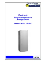
Page 1: ...517672 Electronic Single Temperature Refrigerators Models E373 E450...

Page 2: ...3R 1 FP WH SG 25646 RF450SLDW1 FP AA 25645 RF450SRDW1 FP AA 25647 RF450SRDW1 FP SG HK 23957 E450L D FP WH 24855 E450LW1 FP AA 25051 E450LW1 FP AA 22170 E450L D FP WH 05 22105 E450L D FP WH 07 22101 E4...

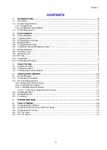
Page 3: ...Alarm 7 2 12 Compressor Starting 7 3 FAULT CODES 7 3 1 Fault Code Table 7 3 2 To Disable Alarm 9 3 3 To Manually Force A Defrost 9 4 SERVICE PROCEDURES 10 4 1 Control Module 10 4 2 Compressor Overload...

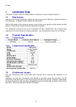
Page 4: ...1 2 1 Compressors Product Model Compressor Part Number Refrigerant Charge E373 450 207119 100 grams R134a 1 2 2 Compressor Specification Brand Matsushita Model SF48C91RAW5 Part Number 207116 Volts 230...

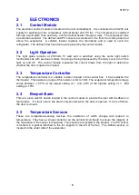
Page 5: ...m the light to determine whether the door is opened or closed 2 3 Temperature Controller The temperature controller is a variable resistor located in the control box It has replaced the thermostat The...

Page 6: ...controlled by the control module which switches it via a relay The defrost interval can vary from between 8 hours and 16 hours of compressor run time depending on the duration time of the last defrost...

Page 7: ...an audio fault alarm will sound when the door is opened The alarm consists of a number of beeps emitted by the beeper located in the control module The number of beeps emitted indicates the fault as...

Page 8: ...tance Secondary Action Replace control module Fault 10 10 beeps Reason The resistance of the PC sensor is outside the normal range 660 Ohms Primary Action Check the sensor connection at the power modu...

Page 9: ...ds 3 3 To Manually Force A Defrost Open the door push the light plunger in and hold in turn the variable resistor control knob to the warmest setting then turn it to the coldest setting within ten sec...

Page 10: ...move all the connectors from the control module Refit the module in reverse order making sure all wiring is secured in the module and the wiring harness is located in the module slot 4 2 Compressor Ov...

Page 11: ...from the power source Remove duct cover Remove fan cover Disconnect fan terminals off fan and remove sensor from housing Remove two screws holding fan housing and unclip fan housing from evaporator c...

Page 12: ...the evaporator duct cover Reassemble the product in reverse order 4 4 Variable Resistor Unplug the product from the power source Remove control box by removing the two screws holding control box in pl...

Page 13: ...517672 13 5 WIRING DIAGRAM...

Page 14: ...ug overload and control module connections Check start and run windings as per specifications Check run capacitor 6 4 PC Too Cold Check resistance of variable resistor Check resistance of PC sensor as...

Reviews: