background image

517672 


14 

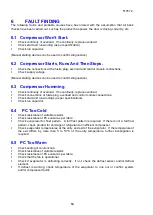
FAULT FINDING 

The  following  faults  and  probable  causes  have  been  listed  with  the  assumption  that  all  basic 
checks have been carried out, such as the product has power, the door is closing correctly, etc. 
 

6.1 

Compressor Won’t Start. 


Check continuity of overload.  If no continuity, replace overload. 


Check start and run winding (as per specification). 


Check run capacitor. 

 
(Manual starting devices can be used to confirm diagnostics.) 
 

6.2  Compressor Starts, Runs And Then Stops. 


Check the connections at the fusite plug, overload and control module connections. 


Check supply voltage. 

 
(Manual starting devices can be used to confirm diagnostics.) 
 

6.3  Compressor Humming 


Check continuity of overload.  If no continuity, replace overload. 


Check connections at fusite plug, overload and control module connections. 


Check start and run windings (as per specifications). 


Check run capacitor. 


6.4 

PC Too Cold 


Check resistance of variable resistor. 


Check resistance of PC sensor as per table. 


Check evaporator for frost pattern.  A full frost pattern is required.  If there is not a full frost 
pattern, check product for shortage of refrigerant or inefficient compressor. 


Check evaporator temperatures at the entry and exit of the evaporator.  If the temperature of 
the  exit  differs  by  more  than  5  to  10ºC  of  the  entry  temperature,  further  investigation  is 
required. 


6.5  PC Too Warm 


Check setting of control knob. 


Check resistance of variable resistor. 


Check resistance of PC sensor as per table. 


Check that the fan is operational. 


Check  if  evaporator  is  defrosting  correctly.    If  not,  check  the  defrost  sensor  and/or  defrost 
element. 


If  defrost  is  working,  check  temperature  of  the  evaporator  to  rule  out  or  confirm  system 
and/or compressor fault/s. 


Summary of Contents for E373

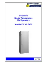
Page 1: ...517672 Electronic Single Temperature Refrigerators Models E373 E450...

Page 2: ...3R 1 FP WH SG 25646 RF450SLDW1 FP AA 25645 RF450SRDW1 FP AA 25647 RF450SRDW1 FP SG HK 23957 E450L D FP WH 24855 E450LW1 FP AA 25051 E450LW1 FP AA 22170 E450L D FP WH 05 22105 E450L D FP WH 07 22101 E4...

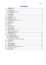
Page 3: ...Alarm 7 2 12 Compressor Starting 7 3 FAULT CODES 7 3 1 Fault Code Table 7 3 2 To Disable Alarm 9 3 3 To Manually Force A Defrost 9 4 SERVICE PROCEDURES 10 4 1 Control Module 10 4 2 Compressor Overload...

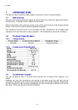
Page 4: ...1 2 1 Compressors Product Model Compressor Part Number Refrigerant Charge E373 450 207119 100 grams R134a 1 2 2 Compressor Specification Brand Matsushita Model SF48C91RAW5 Part Number 207116 Volts 230...

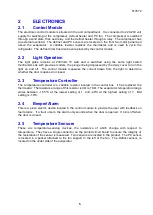
Page 5: ...m the light to determine whether the door is opened or closed 2 3 Temperature Controller The temperature controller is a variable resistor located in the control box It has replaced the thermostat The...

Page 6: ...controlled by the control module which switches it via a relay The defrost interval can vary from between 8 hours and 16 hours of compressor run time depending on the duration time of the last defrost...

Page 7: ...an audio fault alarm will sound when the door is opened The alarm consists of a number of beeps emitted by the beeper located in the control module The number of beeps emitted indicates the fault as...

Page 8: ...tance Secondary Action Replace control module Fault 10 10 beeps Reason The resistance of the PC sensor is outside the normal range 660 Ohms Primary Action Check the sensor connection at the power modu...

Page 9: ...ds 3 3 To Manually Force A Defrost Open the door push the light plunger in and hold in turn the variable resistor control knob to the warmest setting then turn it to the coldest setting within ten sec...

Page 10: ...move all the connectors from the control module Refit the module in reverse order making sure all wiring is secured in the module and the wiring harness is located in the module slot 4 2 Compressor Ov...

Page 11: ...from the power source Remove duct cover Remove fan cover Disconnect fan terminals off fan and remove sensor from housing Remove two screws holding fan housing and unclip fan housing from evaporator c...

Page 12: ...the evaporator duct cover Reassemble the product in reverse order 4 4 Variable Resistor Unplug the product from the power source Remove control box by removing the two screws holding control box in pl...

Page 13: ...517672 13 5 WIRING DIAGRAM...

Page 14: ...ug overload and control module connections Check start and run windings as per specifications Check run capacitor 6 4 PC Too Cold Check resistance of variable resistor Check resistance of PC sensor as...

Reviews: