background image

12

INSTaLLaTION INSTRuCTIONS

Installation

WARNING! 

This product is heavy and requires two persons for installation.

WARNING!

failure to install the screws or fixing device in accordance with these instructions may 

result in electrical hazards. 

The manufacturer is not liable for any damage caused by not following these instructions.

1


Preparing for installation:

Before installing your cooker hood:

Please read the instructions carefully.

Unpack the cooker hood and check that all functions are working.

Ensure that the voltage (V) and the frequency (Hz) indicated on the serial plate 
match the voltage and frequency at the installation site.

Check that the area behind the installation surface to be drilled is clear of any 
electrical cables or pipes, etc.

The stainless steel and glass surfaces of the cooker hood are very easily damaged 
during installation if grazed or knocked by tools. Please take care to protect the 
surfaces during installation.

Protect the hob surface below with cardboard, or the like, to prevent damage 
occurring whilst the cooker hood is being installed above.

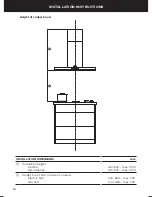
Temporarily mark the height of the bottom of the cooker hood and the centre of the 
hob on the wall according to the information given in the ‘Installation instructions – 
Height of cooker hood’ section.

The wall used for mounting the cooker hood should have sufficient strength and a 
flat surface.

2


Attach chimney brackets and hood mounting screws

Attach the chimney bracket and upper 
chimney bracket (if using the upper chimney) 
in the locations shown in Fig.2 and 3. Use 
the 30 mm screws and expansion plugs if 
attaching to masonry.

Attach the upper hood mounting screws 
in the locations shown in Fig.2 and 3. Use 
the 30 mm screws and expansion plugs if 
attaching to masonry. Ensure that there is a 
2 mm gap between the screw head and the 
wall – see Fig.1.

2 mm

Fig.1

Summary of Contents for HC120BCXB2

Page 1: ...Box wall cooker hood HC60BCXB2 HC90BCXB2 and HC120BCXB2 models GB IE INSTALLATION INSTRUCTIONS USER GUIDE...

Page 2: ......

Page 3: ...THESE INSTRUCTIONS The models shown in this user guide may not be available in all markets and are subject to change at any time For current details about model and specification availability in your...

Page 4: ......

Page 5: ...ith you This use and care manual will answer most of your questions about the set up use and on going maintenance of your Fisher Paykel product however if you require further information about your pr...

Page 6: ...any maintenance or repairs Alterations to the domestic wiring system must only be made by a qualified electrician Failure to follow this advice may result in electrical shock or death IMPORTANT SAFET...

Page 7: ...top of the cooker hood with cardboard or polystyrene during the installation to minimise the risk of damage occurring To reduce the risk of damage occurring to the hob it is recommended that the surf...

Page 8: ...out supervision You must read the details concerning the method and frequency of cleaning There is a fire risk if cleaning is not carried out in accordance with the instructions Never leave frying foo...

Page 9: ...tructions User guide manual 1 Chimney 1 Expansion plug 8 30 mm self tapping screw 8 Upper chimney 1 Cooker hood 1 Ducting adapter 150 mm 1 Chimney bracket 1 Box wall cooker hood HC60BCXB2 HC90BCXB2 an...

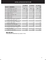
Page 10: ...8 INSTALLATION INSTRUCTIONS Product dimensions G F B A max A min E D K L C I H Power cord location J...

Page 11: ...nless strip 27 27 27 F Width of flue 320 320 320 G Depth of flue 290 290 290 H Distance from centre of ducting outlet to back of product 105 105 105 I Distance from centre of ducting outlet to side of...

Page 12: ...ONS Height of cooker hood N M installation dimensions mm M Installation height Ducted Recirculation min 635 max 1035 min 675 max 1035 N Height top of hob to base of product Electric hob Gas hob min 60...

Page 13: ...d be taken to position the hole correctly For optimal efficiency use rigid or semi rigid ducting for reduced noise and increased airflow Flexible ducting should only be used as a last resort ie in dif...

Page 14: ...sily damaged during installation if grazed or knocked by tools Please take care to protect the surfaces during installation Protect the hob surface below with cardboard or the like to prevent damage o...

Page 15: ...B 250 mm 235 mm C D Upper chimney extension bracket attachment points Chimney bracket attachment points Upper hood attachment points Lower hood attachment points HC60BCXB2 HC90BCXB2 HC120BCXB2 mm A 42...

Page 16: ...14 INSTALLATION INSTRUCTIONS Fig 3 3 Attach ducting adapter Place the ducting adapter onto the hood and screw it in place using the 10 mm screws...

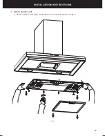
Page 17: ...15 INSTALLATION INSTRUCTIONS 4 Attach hood to wall Remove filters and easy clean plate from hood as shown in Fig 4 Fig 4...

Page 18: ...hten screws Attach lower hood mounting screws to fix hood to wall Reattach easy clean plate and filters 5 Attach ducting Attach ducting to ducting adapter and vent outside 6 Attach chimney Place chimn...

Page 19: ...Efficiency Class A Grease Filtering Efficiency 91 2 Grease Filtering Efficiency Class B Airflow at Min Speed m hr 200 Airflow at Max Speed m hr 525 Airflow at Boost Speed m hr 710 Airborne noise at m...

Page 20: ...he timer on The fan operates for 5 minutes at the current speed and each descending speed before turning off The timer icon flashes red when the filters need cleaning To reset the timer press the butt...

Page 21: ...humidity or coastal environments cleaning should be carried out more frequently Aluminium filters Depending on use and at least once a month the aluminium grease filters should be removed and cleaned...

Page 22: ...is used Note fully saturated carbon filters can become a barrier to air movement therefore limiting cooker hood performance In the event of fire grease laden filters could be flammable and therefore r...

Page 23: ...s and accessories item reference number LED bulb x2 792556 Aluminium filter 791938 Recirculation carbon filter 50031 Recirculation diverter 50032 Ducting kit 150 mm eaves 50033 Ducting kit 150 mm wall...

Page 24: ...ats cockroaches etc 7 Replacement light bulbs B Defects caused by factors other than 1 Normal domestic use or 2 Use in accordance with the product s user guide C Defects to the product caused by accid...

Page 25: ...paykel com Postal address Fisher Paykel Appliances Ltd Maidstone Road Kingston Milton Keynes Buckinghamshire MK10 0BD In Ireland if you need assistance Phone 1800 625 174 or 01 8077960 Fax 1800 635 01...

Page 26: ...24 customer care Complete and keep for safe reference Model Serial No Purchase Date Purchaser Dealer Suburb Town Country...

Page 27: ......

Page 28: ...s in this booklet apply to the specific products and models described at the date of issue Under our policy of continuous product improvement these specifications may change at any time You should the...

Reviews: