37
INFORMATIONS SUR LE PRODUIT
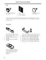
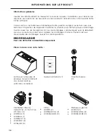
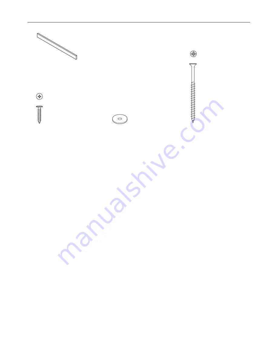
Support en bois (longueur variant selon le modèle)
monté à l’arrière de la hotte. Utilisé au cours de
l’installation
NE PAS JETER
Rondelle plate de
3/4 po (19 mm) (2)
Autres matériaux et outils requis :
●
●
Conduit en métal.
●
●
Ruban d’aluminium (NE PAS utiliser de ruban adhésif en toile).
●
●
Conduit de câblage et raccords de 3/4 po (19 mm) approuvés cULus.
●
●
Serre-câble de 3/4 po (19 mm) approuvé cULus.
●
●
Capuchons de connexion homologués cULus.
●
●
Clapet(s) anti-refoulement d’air, si nécessaire(s).
Vis autotaraudeuse
de 3 po (76 mm) (4)
¾” OD x 3/16” ID
Flat Washer
#10-32
Pan Head
Pozi Drive
Wall Plug
#8 x 3/4”
Truss Head
Philips Drive
Self Tapping Screw
¼-20 x ½”
Pan Head
Philips Drive
Machine Screw
M4 x8
Pan Head
Torx Drive
Machine Screw
#10x 3”
Countersunk
Pozidrive
Self tapping Screw
FP Pro Hood Fasteners
Vis autotaraudeuse
de 3/4 po (19 mm) (8)
¾” OD x 3/16” ID
Flat Washer
#10-32
Pan Head
Pozi Drive
Wall Plug
#8 x 3/4”
Truss Head
Philips Drive
Self Tapping Screw
¼-20 x ½”
Pan Head
Philips Drive
Machine Screw
M4 x8
Pan Head
Torx Drive
Machine Screw
#10x 3”
Countersunk
Pozidrive
Self tapping Screw
FP Pro Hood Fasteners
¾” OD x 3/16” ID
Flat Washer
#10-32
Pan Head
Pozi Drive
Wall Plug
#8 x 3/4”
Truss Head
Philips Drive
Self Tapping Screw
¼-20 x ½”
Pan Head
Philips Drive
Machine Screw
M4 x8
Pan Head
Torx Drive
Machine Screw
#10x 3”
Countersunk
Pozidrive
Self tapping Screw
FP Pro Hood Fasteners
FR
Summary of Contents for HC36 Shell
Page 2: ...English Page 1 29 Français Page 31 59 ...
Page 4: ......
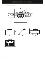
Page 10: ...8 INSTALLATION PREPARATION Product dimensions P O Q A B I C D S R K T E F M N G L J H ...
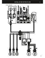
Page 25: ...23 INSTALLATION INSTRUCTIONS Wiring diagram EN ...
Page 32: ......
Page 34: ......
Page 55: ...53 Schéma de câblage INSTRUCTIONS D INSTALLATION FR ...
Page 62: ......
Page 63: ......

