1
1
SAFETY AND WARNINGS
!
WARNING!
Weight Hazard
The appliance is heavy. Please ensure adequate care is taken when installing
the appliance to prevent personal injury.
Weight of the products are:
HPB6028-1 = 14 kg
HPB7528-1 = 17 kg
HPB7548-1 = 21 kg
HPB9028-1 = 19 kg
HPB9048-1 = 23 kg
HPB9048-2 = 31 kg
HPB12048-2 = 35 kg
!
WARNING!
Electric Shock Hazard
Always disconnect the appliance from the mains power supply before
carrying out any maintenance or repairs.
Installation work and electrical wiring must be done by qualified person(s)
in accordance with all applicable codes and standards, including fire-rated
construction. Failure to do so can result in death, electric shock, fire or injury
to persons.
IMPORTANT!
READ THE ENTIRE SET OF INSTRUCTIONS BEFORE INSTALLING OR USING THIS APPLIANCE.
Refer to the user guide for more details on safety and warnings. A copy of the installation
guide and user guide for this product can also be found at fisherpaykel.com.
WARNING!
This appliance must be installed and connected to the mains power supply by a suitably
qualified person according to these installation instructions and in compliance with
any applicable local building and electricity regulations. Failure to install the appliance
correctly could invalidate any warranty or liability claims.
• To comply with electrical safety regulations, the appliance must be plugged into a
socket near the appliance. The socket must be accessible, or have an accessible isolating
switch, to enable the end user to isolate the appliance from the power for the purpose of
internal cleaning or maintenance.
• Ducting accessories are not supplied. All ducting must comply with local requirements
and building codes.
• Attention should be given to ensure that any applicable regulations concerning the
discharge of exhaust air are fulfilled.
• Exhaust air must not be discharged into an existing flue that is used for exhausting
fumes from appliances burning gas or other fuels.
2
PRODUCT INFORMATION
IMPORTANT!
SAVE THIS GUIDE
The models shown in this installation guide may not be available in all markets and are subject to
change at any time. For current details about model and specification availability in your country,
please go to our website fisherpaykel.com or contact your local Fisher & Paykel dealer.
Other required materials and tools:
●
●
Metal ducting
●
●
Aluminium tape (DO NOT use duct tape)
●
●
T20 head screw driver
●
●
Back draft damper(s) if desired
●
●
Please read this manual carefully, and keep it after installation for future reference.
●
●
Keep all packing materials (box and straps) until the unit has been inspected.
●
●
Inspect the product to check there is no shipping damage. If any damage is detected
contact the dealer or retailer you bought the product from to report the damage.
●
●
Fisher & Paykel is not responsible for shipping damage.
INTEGRATED RANGEHOOD
HPB6028-1, HPB7528-1, HPB7548-1, HPB9028-1, HPB9048-1,
HPB9048-2 & HPB12048-2 models
INSTALLATION GUIDE
NZ AU ROW
105464A 02.19
INTEGRATED RANGEHOOD
HPB6028-1, HPB7528-1, HPB7548-1, HPB9028-1, HPB9048-1,
HPB9048-2 & HPB12048-2 models
USER GUIDE
NZ AU ROW
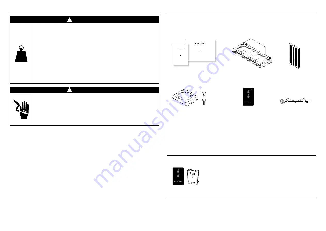
User guide and
Installation guide
Rangehood
Filters
●
●
HPB60 (2)
●
●
HPB75 (2)
●
●
HPB90 (3)
●
●
HPB120 (4)
Optional accessories
Remote control kit – Remote control (1),
Wireless receiver (1)
Remote control
(selected models)
¾” OD x 3/16” ID
Flat Washer
#10-32
Pan Head
Pozi Drive
Wall Plug
#8 x 3/4”
Truss Head
Philips Drive
Self Tapping Screw
¼-20 x ½”
Pan Head
Philips Drive
Machine Screw
M4 x8
Pan Head
Torx Drive
Machine Screw
#10x 3”
Countersunk
Pozidrive
Self tapping Screw
FP Pro Hood Fasteners
●
●
Duct adapter including 8mm T20
drive screws (4) (Selected models)
●
●
HPB9048-2 & HPB12048-2 have a
250mm outlet.
Powercord


