Service Manual 547226: OB30
December 2012
29
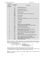
Oven Mode
Knob
Position
(clockwise)
Oven Mode
Display
Description
1
TOP
INNER
Broil/Grill Element Inner.
2
TOP
OUTER
Broil/Grill Element Outer.
3
FAN
ELEMNT
Fan Element and Oven Fan.
4
OVEN
FAN
Oven Cavity Fan.
5
THROAT
ELEMNT
Throat Element
( shown in display, but will not operate)
6
LOWER
ELEMNT
Bake element.
7
COOL
FAN
Cooling Fan.
8
CAT
ELIM
Catalytic Smoke Eliminator
(shown in display, but will not operate)
9
CAVITY
LIGHT
Cavity Lights.
10
LOCK
MOTOR
Lock Motor.
11
VENT
FAN
Vent Fan.
12
NUM
CLEAN
Number Of Pyro Cycles performed.
(Number of times oven has reached 912°F (490°C)
13
CLOCK
TEMP
Clock Module Temperature.
14
PWR MD
TEMP
Power Module Board Temperature.
15
MAX
BOARD
Maximum Temperature recorded on any Board.
(Push “CLEAR” to reset value)
16
CAVITY
TEMP
The Cavity Temperature measured by the sensor.
17
FAULT
CODE
The two most recent Fault Codes are displayed.
(Refer to Note 1)
18
NUM
DAYS
Shows the number of days the product has been on.
19
DOWN
LOAD
Shows that data can now be downloaded.
(Press “CLEAR” to begin Smart Tool Download)
20
TEMP
OFFSET
Adjust temperature to suit customer.
(Press CLEAR to set)
Note: When ‘FAULT CODE’ is selected the oven temperature display will show the two
most recent fault codes in the following temperature knob positions. If ‘OFF’ is displayed
then there are no faults logged.
Temperature Dial Position
Description
0
Most Recent Fault
1
2
nd
Most Recent Fault
If the same fault occurs consecutively it will only be recorded as one fault.
If the Most Recent Fault code is cleared from the log it will then be recorded as the
2
nd
Most Recent Fault. The Most Recent Fault position will be left blank.
Note: To clear a fault code from the log push ‘CLEAR’ when it is displayed in the
temperature display.
Summary of Contents for OB30DDEPX1
Page 2: ......
Page 45: ...Service Manual 547226 OB30 December 2012 45 6 2 Single Oven Wiring Schematic ...
Page 47: ...Service Manual 547226 OB30 December 2012 47 Neutral Circuit ...
Page 48: ...Service Manual 547226 OB30 December 2012 48 Generic High Voltage Circuit ...
Page 49: ...Service Manual 547226 OB30 December 2012 49 Generic Low Voltage Lock Circuit ...
Page 50: ...Service Manual 547226 OB30 December 2012 50 Lighting and Earth Circuit ...
Page 52: ...Service Manual 547226 OB30 December 2012 52 Neutral Circuit ...
Page 53: ...Service Manual 547226 OB30 December 2012 53 Generic High Voltage Circuit ...
Page 54: ...Service Manual 547226 OB30 December 2012 54 Generic Low Voltage Lock Circuit ...
Page 55: ...Service Manual 547226 OB30 December 2012 55 Lighting Earth Circuit ...
Page 74: ...Service Manual 547226 OB30 December 2012 74 8 N O T E S ...


