Service Manual 547226: OB30
December 2012
38
5.17
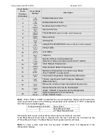
SYMPTOM: Fault Code F5 displayed
CAUSE:
A communications error occurred between the clock module and the power module.
DIAGNOSIS:
Check the connections between the power module and clock module.
If the fault code re-occurs, replace the power module. (refer to Servicing Instructions
Section 7.9)
5.18
SYMPTOM: Fault Code F7 displayed
CAUSE:
A fault occurred with the oven door lock.
DIAGNOSIS:
Check that the oven door lock has not jammed. (refer to Servicing Instructions
Section 7.24)
Check for oven door switch and door lock switch faults. (refer to Section 5.25)
Check for temperature sensor faults. (refer to section 5.23)
Replace the power module if no other component faults can be found. (refer to
Servicing Instructions Section 7.9)
5.19
Tracing Cooling Fan Faults
(Refer to Technical Overview Section 2.8)
PROCEDURE:
If the cooling fan will not start
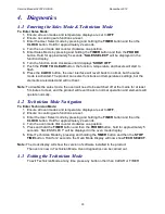
1. Enter Technician Mode diagnostics to test the cooling fan operation. (refer to
Diagnostics Section 4.3)
The cooling fan will operate at low speed in normal operation. When the cooling
fan is turned on in diagnostics it will run at high speed.
2. Test for the correct voltage across the cooling fan contacts or substitute the fan with a
dummy load. Replace the fan if tests are good. (refer to Servicing Instructions
Section 7.16)
3. Check the fan wiring continuity back to the power module.
If the wiring continuity is good then it is likely that the cooling fan is not faulty.
(refer to Symptom Procedure Checklist for further component tests)
If the cooling fan will not turn off
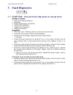
1. Check for temperature sensor faults. (refer to Section 5.23)
The cooling fan will operate at low speed until the cavity temperature is below
300°F (150°C). If the cavity temperature is above 520°F (270°C) the cooling fan
will operate at high speed.
2. Replace the power module if no other component faults can be found, the cooling fan
triac may be faulty. (refer to Servicing Instructions Section 7.9)
Summary of Contents for OB30DDEPX1
Page 2: ......
Page 45: ...Service Manual 547226 OB30 December 2012 45 6 2 Single Oven Wiring Schematic ...
Page 47: ...Service Manual 547226 OB30 December 2012 47 Neutral Circuit ...
Page 48: ...Service Manual 547226 OB30 December 2012 48 Generic High Voltage Circuit ...
Page 49: ...Service Manual 547226 OB30 December 2012 49 Generic Low Voltage Lock Circuit ...
Page 50: ...Service Manual 547226 OB30 December 2012 50 Lighting and Earth Circuit ...
Page 52: ...Service Manual 547226 OB30 December 2012 52 Neutral Circuit ...
Page 53: ...Service Manual 547226 OB30 December 2012 53 Generic High Voltage Circuit ...
Page 54: ...Service Manual 547226 OB30 December 2012 54 Generic Low Voltage Lock Circuit ...
Page 55: ...Service Manual 547226 OB30 December 2012 55 Lighting Earth Circuit ...
Page 74: ...Service Manual 547226 OB30 December 2012 74 8 N O T E S ...

