


Service Manual 547226: OB30
December 2012
40
5.22
Tracing element faults
(Refer to Technical Overview Section 2.10-2.15 & 2.33)
PROCEDURE:
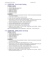
If the element does not turn off (element run-away)
Note: In normal operation the element will cycle (turn on & off) when the cavity
temperature has reached the set point. This can be detected by listening for the
switching noise of the element relay switch on the power module or using a current
meter.
1. Check the temperature sensor is reading the correct temperature. (refer to Section
5.23)
2. If the correct temperature is being read, isolate the supply and check that all the
elements are wired correctly and the element relay switches haven’t short-circuited.
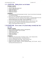
If the element does not heat up
Note: Before testing refer to Technical Overview Sections 2.10-2.15 & 2.33 to find out
which elements are used for each oven mode.
1. Check for a tripped thermal limiter. (refer to section 5.24)
2. Test the element operation in Technician Mode. (refer to Diagnostics Section 4.3)
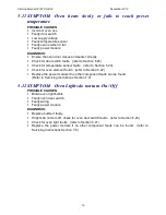
3. If the element does not heat up in Technician Mode, test the resistance of the
element. The appropriate range of resistance for each element is given in Table 5.22
below. Replace the element if its resistance is outside the given range.
Element
Min Resistance (
Ω
Ω
Ω
Ω
)
Max Resistance (
Ω
Ω
Ω
Ω
)
Upper Inner
19
23
Upper Outer
35
50
Lower
34
47
Fan
21
26
Table 5.22
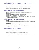
4. Check the continuity of the element wiring back to the power module, including the
thermal limiters and the isolating relay.
Note: The isolating relay is only energized when an oven mode is selected.
5. If the wiring continuity is good, it is likely that the element is not faulty. (refer to
Symptom Procedure Checklist for further component tests)
Summary of Contents for OB30DDEPX1
Page 2: ......
Page 45: ...Service Manual 547226 OB30 December 2012 45 6 2 Single Oven Wiring Schematic ...
Page 47: ...Service Manual 547226 OB30 December 2012 47 Neutral Circuit ...
Page 48: ...Service Manual 547226 OB30 December 2012 48 Generic High Voltage Circuit ...
Page 49: ...Service Manual 547226 OB30 December 2012 49 Generic Low Voltage Lock Circuit ...
Page 50: ...Service Manual 547226 OB30 December 2012 50 Lighting and Earth Circuit ...
Page 52: ...Service Manual 547226 OB30 December 2012 52 Neutral Circuit ...
Page 53: ...Service Manual 547226 OB30 December 2012 53 Generic High Voltage Circuit ...
Page 54: ...Service Manual 547226 OB30 December 2012 54 Generic Low Voltage Lock Circuit ...
Page 55: ...Service Manual 547226 OB30 December 2012 55 Lighting Earth Circuit ...
Page 74: ...Service Manual 547226 OB30 December 2012 74 8 N O T E S ...


