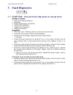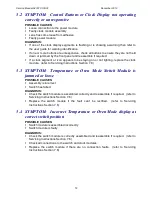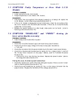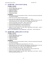
Service Manual 547226: OB30
December 2012
41
5.23
Tracing oven temperature sensor faults
(Refer to Technical Overview Section 2.16)
PROCEDURE:
1. Enter the Technician Mode diagnostics to view the cavity temperature reading. (refer
to Diagnostics Section 4.3)
2. Record the cavity temperature reading and substitute the oven temperature sensor
with a new sensor. (refer to Servicing Instructions Section 7.12)
3. Record the cavity temperature reading from the new sensor.
If there is a significant difference between the two temperature readings (>10
°
F or
>5
°
C), leave the new sensor in.
4. If the two temperature readings are similar (
±
10
°
F or
±
5
°
C) check the temperature
sensor wiring connectors and connection to the power module.
If the wiring is good, refit the original temperature sensor. It is likely the
temperature sensor is not faulty.
5. If the fault persists, test the power module by substituting a 1000 ohm 5% resistor
across pins 1&2 on the ‘Sensors’ connector. (refer to Technical Overview Section
2.25 for pin numbering) The temperature display should read 32°F + 10°F(0°C+ 5°C)
Replace the power module if the displayed reading is incorrect. (refer to Servicing
Instructions Section 7.9)
5.24
Tracing thermal limiter faults
(Refer to Technical Overview Section 2.28)
Note: In the event of a thermal limiter tripping, it is important that the cause be
located and rectified.
PROCEDURE:
1. To locate the tripped thermal limiter check for continuity across the limiter contacts.
2. Replace the faulty thermal limiter/s with one having the same trip temperature. (refer
to Servicing Instructions Section 7.11)
3. Trace the component that is most likely to have caused the thermal limiter to trip.
Note: To do a quick check for a tripped microtemp limiter test for 12
VAC
on the 2 way
connector into the power module from the transformer. (Refer to Technical Overview
Section 2.25)
To trace the likely cause of tripping
1. Determine the likely faulty component.
2. Trace the component fault.
Note: Thermal limiters are positioned in specific areas to detect certain components
failing. The limiter positions and the components they monitor are listed in the Technical
Overview Section 2.28.
These are the most likely causes of a thermal limiter tripping:
Faulty cooling fan (stopped running).
Refer to Section 5.19
Faulty element (element run-away).
Refer to Section 5.22
Faulty temperature sensor (incorrect reading)
Refer to Section 5.23
Summary of Contents for OB30DDEPX1
Page 2: ......
Page 45: ...Service Manual 547226 OB30 December 2012 45 6 2 Single Oven Wiring Schematic ...
Page 47: ...Service Manual 547226 OB30 December 2012 47 Neutral Circuit ...
Page 48: ...Service Manual 547226 OB30 December 2012 48 Generic High Voltage Circuit ...
Page 49: ...Service Manual 547226 OB30 December 2012 49 Generic Low Voltage Lock Circuit ...
Page 50: ...Service Manual 547226 OB30 December 2012 50 Lighting and Earth Circuit ...
Page 52: ...Service Manual 547226 OB30 December 2012 52 Neutral Circuit ...
Page 53: ...Service Manual 547226 OB30 December 2012 53 Generic High Voltage Circuit ...
Page 54: ...Service Manual 547226 OB30 December 2012 54 Generic Low Voltage Lock Circuit ...
Page 55: ...Service Manual 547226 OB30 December 2012 55 Lighting Earth Circuit ...
Page 74: ...Service Manual 547226 OB30 December 2012 74 8 N O T E S ...

