


Service Manual 547226: OB30
December 2012
58
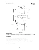
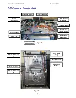
7.6
Function and Temperature Switch Modules
Location: Control Panel
Removal
1. Follow the general servicing instructions for components around the control panel
area. (refer to Section 7.2)
2. Remove the appropriate oven knob.
Note: To best work on the control panel turn it face
down and place blocks of polystyrene under the ends to
elevate it off the working surface.
3. Remove the retaining nut and washer from the faulty
module.
4. Disconnect the wiring harness and transfer to the
replacement module.
5. Remove the faulty module from the lens assembly
and fit the replacement module.
Reassembly
Refit in reverse manner.
Note: Ensure the wiring harness wires are clear of possible crush points during
reassembly.
Follow the reassembly procedure. (refer to Section 7.5)
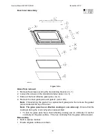
7.7
Function and Temperature L.C.D. Modules and Lenses
Location: Control Panel
L.C.D Modules:
Removal
1. Follow the general servicing instructions for components around the control panel
area. (refer to Section 7.2)
2. Remove the temperature/oven mode knobs and the clock twist button.
3. Disconnect the earth wire and remove the mounting panel.
4. Unclip the faulty module from the retaining lens and lift out.
5. Disconnect the wiring harness and transfer it to the replacement module.
Note: Take care not to leave fingerprints or visible marks on any lens surface.
Reassembly
1. Remove the protective strip from the L.C.D module screen.
2. Refit in reverse manner.
Note: Ensure the wiring harness wires are clear of possible crush points when
reassembling.
Follow the reassembly procedure. (refer to Section 7.5)
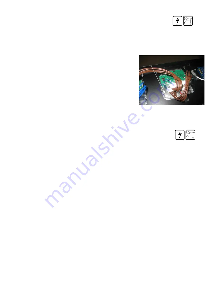
Lens Assembly
Figure 7.6
Summary of Contents for OB30DDEPX1
Page 2: ......
Page 45: ...Service Manual 547226 OB30 December 2012 45 6 2 Single Oven Wiring Schematic ...
Page 47: ...Service Manual 547226 OB30 December 2012 47 Neutral Circuit ...
Page 48: ...Service Manual 547226 OB30 December 2012 48 Generic High Voltage Circuit ...
Page 49: ...Service Manual 547226 OB30 December 2012 49 Generic Low Voltage Lock Circuit ...
Page 50: ...Service Manual 547226 OB30 December 2012 50 Lighting and Earth Circuit ...
Page 52: ...Service Manual 547226 OB30 December 2012 52 Neutral Circuit ...
Page 53: ...Service Manual 547226 OB30 December 2012 53 Generic High Voltage Circuit ...
Page 54: ...Service Manual 547226 OB30 December 2012 54 Generic Low Voltage Lock Circuit ...
Page 55: ...Service Manual 547226 OB30 December 2012 55 Lighting Earth Circuit ...
Page 74: ...Service Manual 547226 OB30 December 2012 74 8 N O T E S ...


