


Service Manual 547226: OB30
December 2012
60
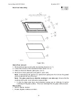
7.9
Power Module
Location: Under the service panel
Removal
1. Follow the general servicing instructions for components around the service panel
area. (refer to Section 7.4)
2. Remove all wires and wire harnesses and transfer them to the replacement power
module. (refer to Technical Overview Section 2.25)
Note: Label the relay switch wires before removing them to ensure the correct
connections are made to the replacement power module.
3. Lift the power module off the seven P.C.B stand-offs.
Note: Use a small pair of needle-nose pliers to
force in the plastic barbs on the P.C.B stand-offs
in order to lift the board up.
Re-assembly
Refit in reverse manner.
Follow the reassembly procedure. (refer to
Section 7.5)
Figure 7.9a
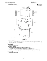
7.10
Power Transformer
Location: Under the service panel
Removal
1. Follow the general servicing instructions for components around the service panel
area. (refer to Section 7.4)
2. Remove the top panel.
3. Remove the two wires from the power supply terminal block and the two wires from
the power module. (refer to Technical Overview Section 2.25)
Note: Ensure that when removing the wires from the terminal block that they are
refitted to the correct terminals.
4. Remove the four transformer retaining screws and lift out the transformer.
Note: Ensure the replacement transformer has the correct voltage and frequency.
Re-assembly
Refit in reverse manner.
Follow the reassembly procedure. (refer to Section 7.5)
Summary of Contents for OB30DDEPX1
Page 2: ......
Page 45: ...Service Manual 547226 OB30 December 2012 45 6 2 Single Oven Wiring Schematic ...
Page 47: ...Service Manual 547226 OB30 December 2012 47 Neutral Circuit ...
Page 48: ...Service Manual 547226 OB30 December 2012 48 Generic High Voltage Circuit ...
Page 49: ...Service Manual 547226 OB30 December 2012 49 Generic Low Voltage Lock Circuit ...
Page 50: ...Service Manual 547226 OB30 December 2012 50 Lighting and Earth Circuit ...
Page 52: ...Service Manual 547226 OB30 December 2012 52 Neutral Circuit ...
Page 53: ...Service Manual 547226 OB30 December 2012 53 Generic High Voltage Circuit ...
Page 54: ...Service Manual 547226 OB30 December 2012 54 Generic Low Voltage Lock Circuit ...
Page 55: ...Service Manual 547226 OB30 December 2012 55 Lighting Earth Circuit ...
Page 74: ...Service Manual 547226 OB30 December 2012 74 8 N O T E S ...


