
Service Manual 547226: OB30
December 2012
63
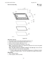
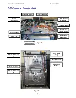
For Front Lamp Assembly
Removal
1. Follow the general servicing instructions for components in the control panel area.
(refer to Section 7.2)
2. Remove the lamp cover and bulb. (refer to Section 7.13)
3. Disconnect the lamp assembly wires from the terminal block in the top panel area.
4. Remove the control panel. (refer to Section 7.2)
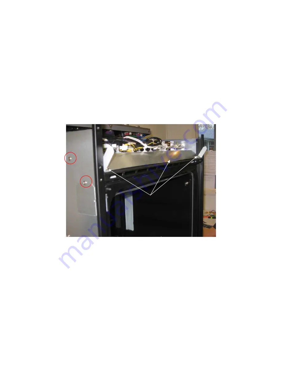
5. Remove the three screws along the front of the wiring panel and the two screws either
side fixing the wiring panel.
6. Lift the front of the wiring panel to access the lamp assembly and wires.
7. Remove the lamp holder retaining screws.
8. Feed the wires through the hole in the wiring panel.
Figure 7.14b
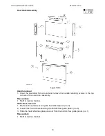
Reassembly
1. Refit in reverse manner.
2. Follow the reassembly procedure. (refer to Section 7.5)
Retaining screws
Summary of Contents for OB30DDEPX1
Page 2: ......
Page 45: ...Service Manual 547226 OB30 December 2012 45 6 2 Single Oven Wiring Schematic ...
Page 47: ...Service Manual 547226 OB30 December 2012 47 Neutral Circuit ...
Page 48: ...Service Manual 547226 OB30 December 2012 48 Generic High Voltage Circuit ...
Page 49: ...Service Manual 547226 OB30 December 2012 49 Generic Low Voltage Lock Circuit ...
Page 50: ...Service Manual 547226 OB30 December 2012 50 Lighting and Earth Circuit ...
Page 52: ...Service Manual 547226 OB30 December 2012 52 Neutral Circuit ...
Page 53: ...Service Manual 547226 OB30 December 2012 53 Generic High Voltage Circuit ...
Page 54: ...Service Manual 547226 OB30 December 2012 54 Generic Low Voltage Lock Circuit ...
Page 55: ...Service Manual 547226 OB30 December 2012 55 Lighting Earth Circuit ...
Page 74: ...Service Manual 547226 OB30 December 2012 74 8 N O T E S ...