
Service Manual 547226: OB30
December 2012
66
7.16
Cooling Fan
Location: Back and top panel areas
Removal
Follow the general servicing instructions for components in the back panel area.
(refer to Section 7.3)
For single ovens and upper cooling fan on double ovens.
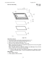
1. Remove the top panel
2. Remove the wires from the cooling fan motor.
3. Remove the two screws on the left of the cooling fan and slide it out from the locating
slot.
4. Remove the four small retaining screws for the cooling fan side brackets and transfer
the brackets to the replacement cooling fan.
Note: Check the replacement cooling fan is specified as in section 2.8.
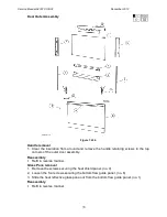
For lower cooling fan on double ovens.
1. Remove the back panel. (refer to Section 7.3)
2. Remove the wires from the cooling fan motor.
3. Remove the two screws on the right of the cooling fan and slide it out from the
locating slot.
4. Remove the four small retaining screws for the cooling fan side brackets and transfer
the brackets to the replacement cooling fan.
Note: Check the replacement cooling fan is specified as in section 2.8.
Reassembly
Refit in reverse manner.
Follow the reassembly procedure. (refer to Section 7.5)
7.17
Vent Fan
Location: In the back panel area
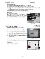
Removal
For single ovens and upper cavity in double ovens
1. Follow the general servicing instructions for components in
the back panel area. (refer to Section 7.3)
2. Remove the vent fan retaining screws.
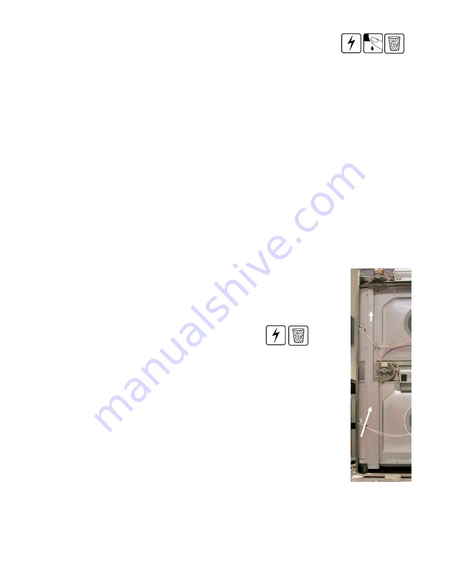
3. Remove the longest section of vent ducting.
4. Remove the vent fan wires.
5. Lift the vent fan out of the vent ducting and rotate counter-
clockwise to clear surrounding parts.
6. Separate the vent fan from the vent tube.
For lower cavity in double ovens
1. Follow the general servicing instructions for components in the back panel area.
(refer to Section 7.3)
2. Remove the vent fan retaining screw.
3. Remove the lower section of vent ducting.
Longest
Ducting
Section
Lower
Ducting
Section
Summary of Contents for OB30DDEPX1
Page 2: ......
Page 45: ...Service Manual 547226 OB30 December 2012 45 6 2 Single Oven Wiring Schematic ...
Page 47: ...Service Manual 547226 OB30 December 2012 47 Neutral Circuit ...
Page 48: ...Service Manual 547226 OB30 December 2012 48 Generic High Voltage Circuit ...
Page 49: ...Service Manual 547226 OB30 December 2012 49 Generic Low Voltage Lock Circuit ...
Page 50: ...Service Manual 547226 OB30 December 2012 50 Lighting and Earth Circuit ...
Page 52: ...Service Manual 547226 OB30 December 2012 52 Neutral Circuit ...
Page 53: ...Service Manual 547226 OB30 December 2012 53 Generic High Voltage Circuit ...
Page 54: ...Service Manual 547226 OB30 December 2012 54 Generic Low Voltage Lock Circuit ...
Page 55: ...Service Manual 547226 OB30 December 2012 55 Lighting Earth Circuit ...
Page 74: ...Service Manual 547226 OB30 December 2012 74 8 N O T E S ...