840653
68
12.3.22
Replacement Of Filter Sensor
Located on the filter drier.
•
Remove the front panels.
•
Remove the cabinet from its enclosure.
•
Remove the bottom air grill cover from the evaporator.
•
Cut the cable tie securing the sensor and remove the sensor from its location.
•
Replacement of the new sensor is done by cutting the wire off the new sensor about 50mm from the
sensor, stripping the wire back about 10mm, stripping the old sensor wiring back about 10mm, and
soldering the new sensor to the old wiring, making sure both connecting wires are not shorting but are
insulated with heat shrink sleeving.
Refit in reverse order.
12.3.23
Replacement Of Compartment Sensor
Located on the rear compartment wall at the top centre.
•
Remove the drawer front panel (refer to Section 12.3.8).
•
Cut the cable tie securing the sensor and remove the sensor from its location.
•
Replacement of the new sensor is done by cutting the wire off the new sensor about 50mm from the
sensor and stripping the wire back about 10mm. Cut the old sensor wiring off close to the sensor and
strip the old wiring back about 10mm. Slide the heat shrink sleaving over each wire and solder the new
sensor to the old wiring. Heat the heat shrink sleaving, making sure both connecting wires are not
shorting but are insulated with the heat shrink sleeving.
Refit in reverse order.
12.3.24
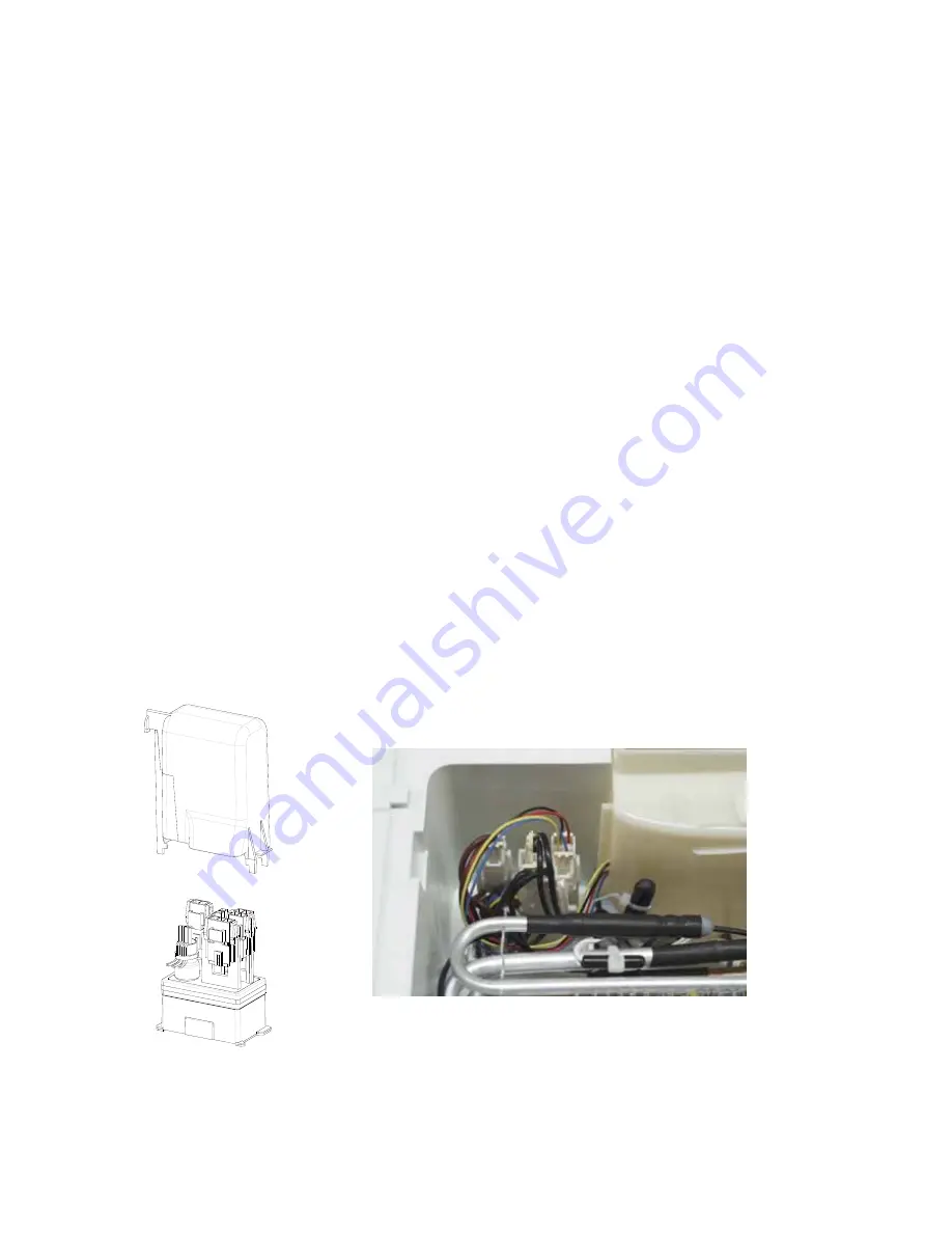
Removal And Refitment Of Air Bell
The air bell covers a number of plug and harness connections that are contained in the evaporator sump of
the CoolDrawer. The air bell by its nature prevents water from the defrosting of the evaporator coming into
contact with the plugs and sockets. Removing the evaporator cover (refer to Section 12.3.17) gives access
to the air bell that is located at the rear of the sump on the left hand side. It is held in place by a clip.
The position in which the plug connections are placed on the mounting post is important to enable the air bell
cover to be refitted.
Air Bell
Mounting Post Base
Summary of Contents for RB36S25MKIW
Page 1: ...840653 Service Manual CoolDrawer Models RB36S25MKIW RB90S64MKIW ...
Page 12: ...840653 12 3 4 Integrated Panel Preparation ...
Page 14: ...840653 14 3 5 Create Cut Outs In Frame 3 6 Locate And Secure Install Brackets ...
Page 15: ...840653 15 3 7 Attach Inlet And Outlet Vent Ducts 3 8 Attach Power Cord And Trim Brackets ...
Page 16: ...840653 16 3 9 Move Product Into Cavity 3 10 Fit Drawer Panel Attachment Hooks ...
Page 17: ...840653 17 3 11 Attach Drawer Panel To Front Of Drawer ...
Page 18: ...840653 18 3 12 Secure Trim Brackets To Cabinetry 3 13 Attach Trims To Sides Of Cabinetry ...
Page 19: ...840653 19 3 14 Attach False Panel 3 15 Check Operation ...
Page 53: ...840653 53 11 WIRING DIAGRAMS Ω Ω Ω Ω Ω Ω Ω Ω Ω Ω ...
Page 54: ...840653 54 ...
Page 77: ...840653 77 ...


