321037
20
5.4.6
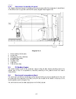
Compressor Compartment Layout
The diagram below will assist in identifying the various pipes within the compressor compartment.
It should be read in conjunction with the full system diagram (See Diagram 5.3).
Diagram 5.4.6
1. Service tube (process pipe).
2. Suction
line.
3. Discharge line into condenser.
4. Condenser to mullion.
5. Mullion to filter.
6. Capillary
tube.
7. Filter
dryer.
8. Filter process pipe.
5.5
FC Mullion Heater
The mullion heater is part of the condenser copper tubing (mullion heater) providing heat to the
gasket area of the FC compartment, preventing sweating of the gasket around the freezer
compartment.
5.6
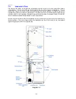
Provision Compartment Duct
The duct covers provide an air passage up the rear wall of the provision compartment for the cold
air drawn from the evaporator by means of the PC fan located at the bottom of the duct in the
divider partition (refer to Diagram 5.6).
The duct channel uses moulded polystyrene duct for this purpose
8
2
3
7
6
1
4
5
Summary of Contents for RF175W
Page 1: ...321037 Service Manual Active Smart Refrigerator Freezer Models RF195A RF175W...
Page 19: ...321037 19 5 4 5 Condenser Mullion Layout Diagram 5 4 5...
Page 77: ...321037 77 15 WIRING DIAGRAM 15 1 RF175 Wiring Diagram...
Page 78: ...321037 78 15 2 RF175 Control Module Wiring Diagram...
Page 79: ...321037 79 15 3 RF175 Ice Water Wiring Diagram...
Page 80: ...321037 80 15 4 RF175 Ice Water Control Module Wiring Diagram...
Page 81: ...321037 81 15 5 RF195A Ice Water Wiring Diagram...
Page 82: ...321037 82 15 6 RF195A Ice Water Control Module Wiring Diagram...

