321037
24
6.1.2 Door
Switches
“Reed” switches are used to detect the opening and closing of the doors. Small magnets are built
into the PC doors and FC drawer, which activate the reed switches. The reed switches are
encapsulated within a plastic housing, which is clipped under the plastic covers on the base and
cross rails.
6.1.3 Defrost
Heater
A heating element (refer to Diagram 6.1.3) is used to defrost the ice accumulated on the
evaporator. The defrosts are adaptive to the usage and environment and are controlled by the
power/control module and sensed by the defrost sensor located on the evaporator chassis
registering 8
O
C (46.4
O
F) before terminating the defrost heater element. Previous defrost history,
the number of door openings, and the compressor run time are used to determine the interval
between defrosting. The typical time interval for defrosts is between 12 hours and 1 day. However
it can be as short as 3 hours or as long as 70.8 hours depending on the usage and environment.
Diagram 6.1.3
6.1.4 Thermal
Fuse
There are two thermal fuses mounted in the wiring harness of the defrost element, having a
tripping temperature of 72
O
C (161.6
O
F). Once open circuit, they cannot be reset. Replacement is
part of the element heater assembly.
These fuses in both leads of the element protect the refrigerator from any over-heating through
failure of the element itself or a triac failure in the power/control module. Both sides are protected
in case phase and neutral are reversed.
NOTE: Care should be taken if manually defrosting the evaporator using a heat gun, that the
thermal fuses are not over heated.
6.1.5
Low Ambient Heater
In low ambient temperatures, a 12 Volt, 7 Watt low power heater is used to keep the temperature
in the provision compartment above freezing. The ambient heater is controlled by the
power/control module, which uses pulse width modulation (PWM) to run the heater at 58% to give
4.1 watts of heat. The ambient heater is situated in the divider partition. The element has the
purpose of warming the base of the PC if the ambient becomes too low, hence in the “B” models,
the element is on when the cabinet cycles off, as the crispers could freeze. The heater will always
be switched off during defrosting. There may be less than 4 cycles in the calculation if a defrost
has occurred or there were long cycle times.
Summary of Contents for RF175W
Page 1: ...321037 Service Manual Active Smart Refrigerator Freezer Models RF195A RF175W...
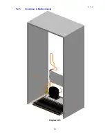
Page 19: ...321037 19 5 4 5 Condenser Mullion Layout Diagram 5 4 5...
Page 77: ...321037 77 15 WIRING DIAGRAM 15 1 RF175 Wiring Diagram...
Page 78: ...321037 78 15 2 RF175 Control Module Wiring Diagram...
Page 79: ...321037 79 15 3 RF175 Ice Water Wiring Diagram...
Page 80: ...321037 80 15 4 RF175 Ice Water Control Module Wiring Diagram...
Page 81: ...321037 81 15 5 RF195A Ice Water Wiring Diagram...
Page 82: ...321037 82 15 6 RF195A Ice Water Control Module Wiring Diagram...

