321037
26
6.1.7
Lights (PC & FC)
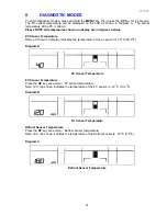
Two 12 volt, 10 watt halogen lamps are used in the PC and one in the FC. To prevent
overheating, the lamp is turned off after 5 minutes of the door being left open. The power / control
module controls this. If lamps are replaced, they must not exceed 10 watts, or they will overload
the power/control module.
Diagram 6.1.7
Note:
It is important that the lamp pins are tight in the lamp socket. The lamp should not be
touched with fingers, as this will shorten its life.
6.1.8
Thermistor Temperature Sensors
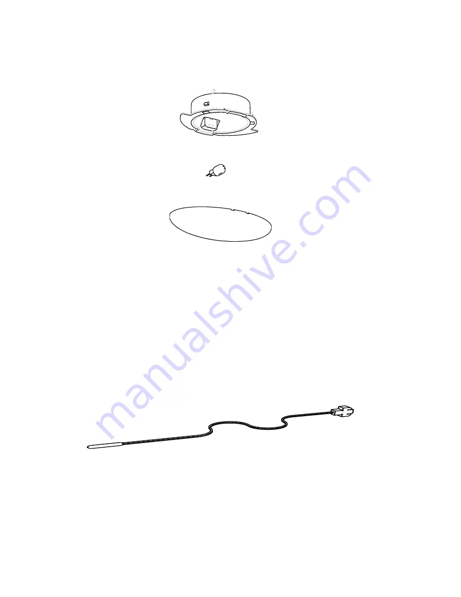
These sensors are used to monitor temperatures within the refrigerator. There are three:
1. Defrost sensor mounted above the evaporator, used to measure the temperature during
defrost.
2. FC sensor mounted on the evaporator coil cover, used to measure the temperature in FC.
3. PC sensor mounted in the PC on the duct cover and used to sense the PC temperature.
Thermistor sensors are used for temperature measurement. Their electrical resistance changes
as the temperature changes. The table below lists some typical resistance values. The
temperature can be read on the display once the diagnostic mode is entered.
Diagram 6.1.8
Summary of Contents for RF175W
Page 1: ...321037 Service Manual Active Smart Refrigerator Freezer Models RF195A RF175W...
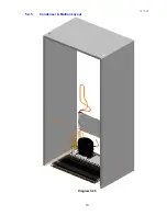
Page 19: ...321037 19 5 4 5 Condenser Mullion Layout Diagram 5 4 5...
Page 77: ...321037 77 15 WIRING DIAGRAM 15 1 RF175 Wiring Diagram...
Page 78: ...321037 78 15 2 RF175 Control Module Wiring Diagram...
Page 79: ...321037 79 15 3 RF175 Ice Water Wiring Diagram...
Page 80: ...321037 80 15 4 RF175 Ice Water Control Module Wiring Diagram...
Page 81: ...321037 81 15 5 RF195A Ice Water Wiring Diagram...
Page 82: ...321037 82 15 6 RF195A Ice Water Control Module Wiring Diagram...

