321037
3
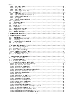
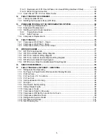
CONTENTS
1
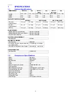
SPECIFICATIONS...................................................................................................................... 6
1.1
Cabinet Specifications......................................................................................................... 6
1.2
Compressor Specifications.................................................................................................. 6
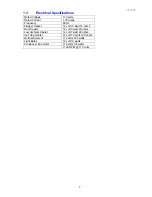
1.3
Electrical Specifications....................................................................................................... 7
2
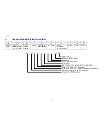
MODEL NUMBER IDENTIFICATION ........................................................................................ 8
3
SERVICING REQUIREMENTS .................................................................................................. 9
3.1
Specialised Service Tools ................................................................................................... 9
3.1.1
Static Strap................................................................................................................... 9
3.1.2
Interface Pen Mk 2 ....................................................................................................... 9
3.2
Health & Safety ................................................................................................................... 9
3.2.1
Good Work Practices.................................................................................................... 9
3.2.2
Environmental Health and Safety ................................................................................. 9
3.2.3
Good Practice and Safety............................................................................................. 9
4
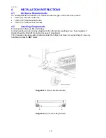
INSTALLATION INSTRUCTIONS............................................................................................ 10
4.1
Air Space Requirements ................................................................................................... 10
4.2
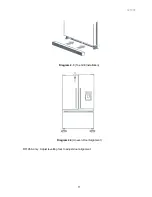
Levelling Components....................................................................................................... 10
4.3
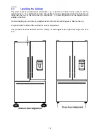
Levelling the Cabinet......................................................................................................... 12
5
THEORY OF OPERATION....................................................................................................... 14
5.1
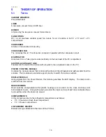
Terms ................................................................................................................................ 14
5.2
Defrost Cycle..................................................................................................................... 15
5.3
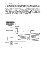
The Refrigeration Cycle..................................................................................................... 16
5.4
Servicing Features ............................................................................................................ 17
5.4.1
Condensate Disposal ................................................................................................. 17
5.4.2
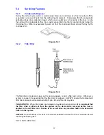
Filter Drier................................................................................................................... 17
5.4.3
Condenser.................................................................................................................. 18
5.4.4
Condenser Fan........................................................................................................... 18
5.4.5
Condenser & Mullion Layout ...................................................................................... 19
5.4.6
Compressor Compartment Layout ............................................................................. 20
5.5
FC Mullion Heater ............................................................................................................. 20
5.6
Provision Compartment Duct............................................................................................. 20
5.7
Divider Partition ................................................................................................................. 22
6
ELECTRONICS SECTION ....................................................................................................... 23
6.1
Function Overview............................................................................................................. 23
6.1.1
Power / Control Module .............................................................................................. 23
6.1.2
Door Switches ............................................................................................................ 24
6.1.3
Defrost Heater ............................................................................................................ 24
6.1.4
Thermal Fuse ............................................................................................................. 24
6.1.5
Low Ambient Heater ................................................................................................... 24
6.1.6
PC/FC Fans................................................................................................................25
6.1.7
Lights (PC & FC) ........................................................................................................ 26
6.1.8
Thermistor Temperature Sensors............................................................................... 26
6.1.9
Flapper Door Heater................................................................................................... 27
7
DISPLAY INTERFACE............................................................................................................. 28
7.1
Display Interface (Button Descriptions) ............................................................................. 28
7.2
Display Functional Schematic ........................................................................................... 28
7.3
Display Interface Features ................................................................................................ 29
7.4
Features ............................................................................................................................ 29
7.4.1
Icemaker On / Off .......................................................................................................29
7.4.2
Freezer Chill Mode ..................................................................................................... 29
7.4.3
Bottle Chill Mode ........................................................................................................ 29
7.4.4
Water Dispensing ....................................................................................................... 29
7.4.5
Sabbath Mode ............................................................................................................ 30
Summary of Contents for RF175W
Page 1: ...321037 Service Manual Active Smart Refrigerator Freezer Models RF195A RF175W...
Page 19: ...321037 19 5 4 5 Condenser Mullion Layout Diagram 5 4 5...
Page 77: ...321037 77 15 WIRING DIAGRAM 15 1 RF175 Wiring Diagram...
Page 78: ...321037 78 15 2 RF175 Control Module Wiring Diagram...
Page 79: ...321037 79 15 3 RF175 Ice Water Wiring Diagram...
Page 80: ...321037 80 15 4 RF175 Ice Water Control Module Wiring Diagram...
Page 81: ...321037 81 15 5 RF195A Ice Water Wiring Diagram...
Page 82: ...321037 82 15 6 RF195A Ice Water Control Module Wiring Diagram...


