321037
35
7.9 Diagnostics
A spanner symbol and LCD fault code will appear automatically if there is a fault in the temperature
measuring system, defrost system, fans or low ambient heater. (Refer to the diagram below.)
When the PC door is opened, an alarm will sound. The number of beeps also indicates the fault
code. Pressing any of the control buttons can deactivate these alarms.
Example: When a fault develops, the LCD fault code appears with the spanner.
After rectifying the problem, the fault code and spanner will disappear. Faults are only rectified
when that feature is used. So in the case of a defrost fault, the code will remain until a defrost is
initiated and it is successful.
7.10 Fault
Codes
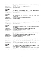
Fault Code 1
Reason:
On the last power up, the power module failed self test.
Primary Action:
Replace power module.
Fault Code 2
Reason:
The previous 2 defrosts were aborted after
40 minutes.
Primary Action:
Check defrost element assembly in the FC. If faulty, replace.
Fault Code 3
Reason:
The resistance of all the temperature sensors are outside the normal range
(> 45K Ohms).
Primary Action:
Check the 6-way RAST connector at the power module.
Secondary Action:
Re-terminate the 6-way RAST connector.
Tertiary Action:
Replace the power module.
Fault Code 4
Reason:
The resistance of all the temperature sensors are outside the normal range
(< 660 Ohms).
Primary Action:
Check the 6-way RAST connector at the power module.
Secondary Action:
Re-terminate the 6-way RAST connector.
Tertiary Action:
Replace the power module.
Fault Code 5
Reason:
The resistance of the FC sensor is outside the normal range
(> 45K Ohms).
Primary Action:
Check the sensor connection at the power module.
Secondary Action:
Replace the sensor.
Fault Code 6
Reason:
The resistance of the FC sensor is outside the normal range
(<660 Ohms).
Primary Action:
Check the sensor connection at the power module.
Secondary Action:
Replace the sensor.
Summary of Contents for RF175W
Page 1: ...321037 Service Manual Active Smart Refrigerator Freezer Models RF195A RF175W...
Page 19: ...321037 19 5 4 5 Condenser Mullion Layout Diagram 5 4 5...
Page 77: ...321037 77 15 WIRING DIAGRAM 15 1 RF175 Wiring Diagram...
Page 78: ...321037 78 15 2 RF175 Control Module Wiring Diagram...
Page 79: ...321037 79 15 3 RF175 Ice Water Wiring Diagram...
Page 80: ...321037 80 15 4 RF175 Ice Water Control Module Wiring Diagram...
Page 81: ...321037 81 15 5 RF195A Ice Water Wiring Diagram...
Page 82: ...321037 82 15 6 RF195A Ice Water Control Module Wiring Diagram...


