85
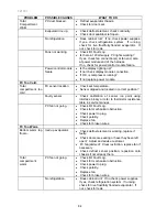
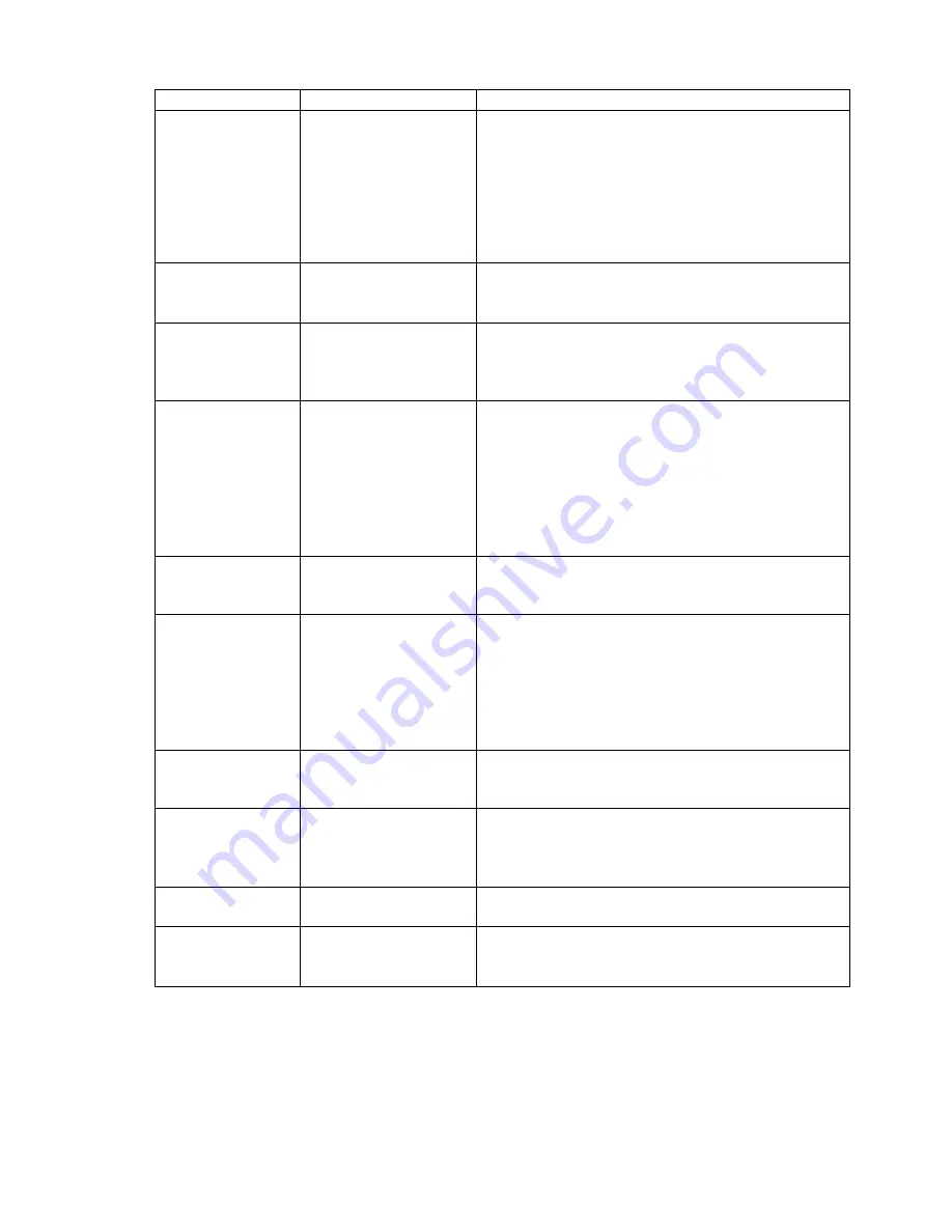
PROBLEM
POSSIBLE CAUSES
WHAT TO DO
Total Cabinet
Too Warm.
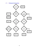
No refrigeration.
•
Does cabinet run? If no, check power
supplies. If yes, check refrigeration system. If
running, check for live frost/fully flooded
evaporator. If not, check for leak.
•
Compressor is not running? Check
power/control module voltage outputs. Check
compressor.
•
Check reed switches are working OK.
FC Cooling
PC Warming.
Iced up evaporator.
•
Check defrost circuit continuity.
•
Doors sealing, adjust.
•
PC fan is running? If not, refer PC too warm.
Iced up return duct.
•
De-ice duct area.
•
Check PC duct insulation for good seal in
return duct.
•
Check doors are sealing.
Alarm On.
Defrost heater.
•
Check display for any fault code.
•
Check defrost element continuity.
•
Put cabinet into manual defrost, wait for
defrost relay to “click” on (2 ½ minutes after
pressing buttons).
•
If no “click”, check power/control module.
•
If “click” heard, check the defrost heater 230v
output at the power/control module.
Sensors.
•
Check display for fault codes 0 to 5
•
Sensors above or below limit? Refer
thermistor sensors Section 6.1.8.
Door switch fault.
•
Check that no fault code is shown on the
display.
•
Check that PC/FC doors activate reed
switches.
•
Check also reed switches with magnet.
•
Check wiring harness to power/control
module.
Fault Displayed -
No Alarm.
Display showing fault
code, but no alarm
sounding.
•
Alarm has been switched off by user.
•
Piezo alarm faulty? Replace power/control
module.
FC Light Not
Functioning.
Blown bulb.
•
Check power supply to socket 7Volts. If nil,
check plug at display module.
•
Check continuity of bulb. If nil, replace.
•
Check reed switch operations.
Cabinet
type.
•
Power/console module not initialised? Close
FC door and press compartment select button.
Poor
connection.
•
Spread halogen bulb legs.
•
Lamp holder? Replace where possible.
•
Connector on display module.
Summary of Contents for RF175W
Page 1: ...321037 Service Manual Active Smart Refrigerator Freezer Models RF195A RF175W...
Page 19: ...321037 19 5 4 5 Condenser Mullion Layout Diagram 5 4 5...
Page 77: ...321037 77 15 WIRING DIAGRAM 15 1 RF175 Wiring Diagram...
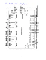
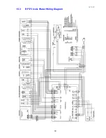
Page 78: ...321037 78 15 2 RF175 Control Module Wiring Diagram...
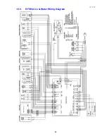
Page 79: ...321037 79 15 3 RF175 Ice Water Wiring Diagram...
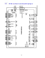
Page 80: ...321037 80 15 4 RF175 Ice Water Control Module Wiring Diagram...
Page 81: ...321037 81 15 5 RF195A Ice Water Wiring Diagram...
Page 82: ...321037 82 15 6 RF195A Ice Water Control Module Wiring Diagram...

