background image

24

!3

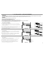
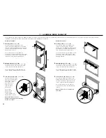
   ASSEMBLE DOOR PANEL SET

The assembly of Fisher & Paykel kits (EZKleen stainless steel door panels) and custom door panels are outlined below. For Fisher & Paykel kits, only remove the protective film for handle 
installation. This will protect the finish of the door panels until installation is complete.

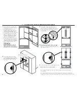
Mounting handle 

(refer to 

A

)

For Fisher & Paykel door panel sets, 
remove the plastic plugs from the handle 
holes x4. Align the handle to the holes and 
secure with screw handle x4 (M5 x 25 pan 
head socket screws).

For custom panels, ensure handle is 
secured 2 9/16” (65 mm) from the inner edge 
of the panel to the center – this will avoid 
interference with bracket installation.

Hanging bracket 

(refer to 

B

)

For Fisher & Paykel door panel sets, align 
the bracket to the holes and secure with 
screws x4 (M5 x 14 Mush Phillips SS).

For custom panels, secure bracket with 
screws x4 (#8 x 16 Mush washer screws).

Side brackets and straps 

(refer to 

C

)

For Fisher & Paykel door 
panel sets, align bracket 
and strap to the holes 
on the side of the 
panel and secure 
with screws x2 
(M5 x 14 Mush 
Phillips SS).

For custom 
panels, secure 
bracket with 
screws x2 (#8 x 16 
Mush washer screws).

Repeat this process for all 

brackets and straps, and remaining 

French door panel.

C

A

B

French door panels

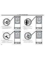
Drawer door panel

Mounting handle 

(refer to 

D

)

For Fisher & Paykel door panel sets, 
remove the plastic plugs from the 
handle holes x4. Align the handle to the 
holes and secure with screw handle x4 
(M5 x 25 pan head socket screws).

For custom panels, ensure handle screw 
heads are counter sunk into the back 
of the panel to avoid interference with 
hanging bracket.

Hanging bracket 

(refer to 

E

)

For Fisher & Paykel door panel sets, align 
the bracket to the holes and secure with 
screws x6 (M5 x 14 Mush Phillips SS).

For custom panels, secure bracket with 
screws x6 (#8 x 16 Mush washer screws).

Side brackets and straps 

(refer to 

F

)

For Fisher & Paykel door panel sets, 
align bracket and strap to the holes on 
the side of the panel and secure with 
screws x2 (M5 x 14 Mush Phillips SS).

For custom panels, secure bracket 
with screws x2 (#8 x 16 Mush washer 
screws).

Repeat this process for all brackets 

and straps.

D

E

F

Summary of Contents for RS36A80J

Page 1: ...ActiveSmart Built in refrigerator RS36A80J and RS36A80U models US CA INSTALLATION INSTRUCTIONS 843155 B 08 15 www fisherpaykel com Framed cabinetry...

Page 2: ......

Page 3: ...4 mm ATTACH ANTI TIP BRACKET ATTACH TOP TRIM FRAMED CABINETRY Framed Aligns the product with the frame of the cabinetry Note shown with custom panel attached to fridge 9 ATTACH SIDE BASE BRACKETS AND...

Page 4: ......

Page 5: ...ur refrigerator and interrupt the power supply The use of a GFCI is not recommended with this product Location Your refrigerator should not be located in direct sunlight or next to any heat generating...

Page 6: ...10 M5 x 10 pan head Phillips screw 10 Door panel fittings Included with standard appliance 8 x 16 mush washer screw 46 M8 stud 6 Side cover 10 Top cover 4 M8 nut 6 M8 washer 6 Anti tip bracket fitting...

Page 7: ...M5 x 25 pan head socket screw 12 Non Water dispensing French panel 1 Ice Water French panel 1 Drawer panel 1 Model number RD3680U or RD3684U Non Water dispensing French panels 2 Drawer panel 1 Model...

Page 8: ...mm pan head screw 3 Side trim 2 Top trim joining bracket 2 Installation aiders 4 required for Frameless cabinetry installation M5 nut 4 M5 x 8 countersunk Phillips screw 12 Top trim 1 Side trim brack...

Page 9: ...E OF HOSE AND POWER CORD Power cord excl plug 803 4 2051 mm RIGHT HAND SIDE Power cord excl plug 803 4 2051 mm LEFT HAND SIDE Power cord excl plug 311 2 800 mm Water inlet hose 53 1350 mm Water inlet...

Page 10: ...manufactured and fitted by cabinetmaker maximum thickness 19 mm CAVITY DIMENSIONS inches mm A Overall height of cavity 80 84 2032 2134 B Overall width of cavity 36 914 C Overall depth of cavity 243 4...

Page 11: ...es to be manufactured and fitted by cabinetmaker Measured from front cabinetry edge C A B B A D Wall Wall 90 DOOR OPENING 115 DOOR OPENING FULL ROTATION For 90 door swing a hinge limiting pin is suppl...

Page 12: ...e of product 5 32 4 G Overall depth of product excluding front door panels 233 4 603 H Depth of toe kick measured from front of door panels 43 4 120 I Height of toe kick 4 102 J Height of bottom drawe...

Page 13: ...e of product 5 32 4 G Overall depth of product excluding front door panels 233 4 603 H Depth of toe kick measured from front of door panels 43 4 120 I Height of toe kick 4 102 J Height of bottom drawe...

Page 14: ...rance to adjacent wall 90 reduced internal access 411 32 110 Measured from front cabinetry edge D A B C B C A E Wall Wall 90 DOOR OPENING 115 DOOR OPENING FULL ROTATION For 90 door swing a hinge limit...

Page 15: ...less steel braided hose Pressure Minimum 22 psi 150 kPa Maximum 120 psi 827 kPa 68 F 20 C Note electrical connection can be located in an adjacent cabinet to either side of the fridge or above the fri...

Page 16: ...of custom panels min 3 4 min 16 19 Maximum weight of an individual top door panel 22 pounds 10 kg Maximum weight of bottom drawer panel 241 4 pounds 11 kg Custom door panels to be manufactured and fi...

Page 17: ...er bottom corner as the reference point Ensure handle is mounted 29 16 from inner edge of panel to the center this will avoid interference with brackets 13 8 165 16 25 32 431 32 615 16 2415 16 2629 32...

Page 18: ...tion 1 Project the end of the above finished enclosure to the center of the back wall and subtract 27 16 62 mm This will locate the contact surface between the bracket and the appliance refer to A Ens...

Page 19: ...ed we recommend fastening a solid spacer wooden beam etc behind the bracket 1 Ensure the length of the spacer corresponds to the enclosure s width Always secure the spacer to existing studs on the enc...

Page 20: ...behind the existing appliance trim Bring the top trim forward and insert screw heads through the key holes of the joining brackets refer to A 13 330 mm 13 330 mm 13 330 mm 13 330 mm 1 Ensure all exter...

Page 21: ...of the appliance attach the LH side bracket to the dedicated threaded holes and secure with screws x2 M5 x 8 countersunk Phillips screws Repeat this process on the RH side of the appliance LH orientat...

Page 22: ...should be accessible 1 Ensure the refrigerator is NOT plugged into a power supply Locate isolating faucet for water connection cold water supply only Tee and faucet fittings are not supplied Position...

Page 23: ...to correct position Stop midway reach through base to locate power cord Pull power cord through the front left side of the appliance refer to F tucking it neatly in the left side of the base refer to...

Page 24: ...oth sides Place a ruler on the front of the product to check flushness top and bottom left and right This step will help ensure the refrigerator is level with the adjacent cabinetry IMPORTANT Failure...

Page 25: ...e in the locked position US 80 PLUMBING INSTALLATION SCALE 1 000 SCALE 1 000 SCALE 1 000 Front view 3 Turn 90 clockwise to tighten Remove filter cartridge tool and close freezer drawer 4 Installing ki...

Page 26: ...t and strap to the holes on the side of the panel and secure with screws x2 M5 x 14 Mush Phillips SS For custom panels secure bracket with screws x2 8 x 16 Mush washer screws Repeat this process for a...

Page 27: ...o A 5 Connect display harness onto the refrigerator door by inserting firmly until you feel it clip securely refer to B On the external display enable the dispenser lock this will help prevent any wat...

Page 28: ...ont of the product to check flushness top and bottom left and right refer to drawing below Ensure the gap between the top of the door panel and the top cabinetry is no greater than 7 mm To reduce this...

Page 29: ...e refer to the User Guide supplied with this appliance Water dispenser initiation Ice Water models only To flush the water filtration system before use Press the water dispenser pad until water dispen...

Page 30: ...Secure the center of each fixing bracket to the side of the adjacent wall with screws x2 8 x 19 twin thread screws Repeat this process for the remaining brackets 3 Slide screw cover in between the fix...

Page 31: ...cket screws mid way and bring forward refer to A and B Repeat this process on the opposite side 5 Place toe kick in front of the brackets and gently push towards the appliance until flush with surroun...

Page 32: ...ES THROUGH DIMPLES 2 USE PROVIDED SCREWS TO FIX G 3 MATCHING HOLES ON PLASTIC P B DETAIL D SCALE 2 1 IF TOEKICK IS HIGHER THAN 4 USE SIDE CUTTER TO 1 CUT UNREQUIRED VANES FROM DOTTOM DRILL HOLES THROU...

Page 33: ...brackets on each side refer to A for bracket locations Open the appliance doors Measure 2 50 mm from the front face of the appliance from behind the doors to the front of the alcove and accurately mar...

Page 34: ...s for the trim to locate Ensure the trim is engaged at both points refer to D Repeat this process for the remaining side trim Correct visual gaps by loosening side trim screws and moving trim within c...

Page 35: ...force is required 1 To ensure the French doors shut on their own when pushed within the self close activation range the hinge tensioning screws need to be tightened The hinge tensioning screw is locat...

Page 36: ...liance is level Ensure the appliance is securely fastened to the cabinetry with the supplied anti tip bracket and fittings Ensure the doors drawer can open and close freely with no resistance from sur...

Page 37: ......

Page 38: ...s in this booklet apply to the specific products and models described at the date of issue Under our policy of continuous product improvement these specifications may change at any time You should the...

Reviews: