321023
77
11.1.4
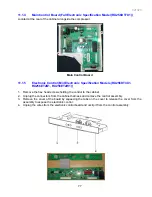
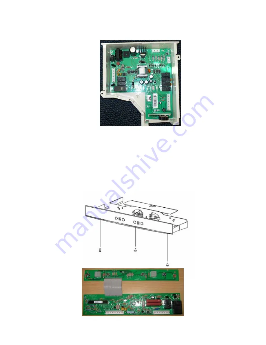
Main Control Board (Full Electronic Specification Model (RX256DT7X1))
Located at the rear of the cabinet alongside the compressor.
Main Control Board
11.1.5
Electronic Control (Mid Electronic Specification Models (RX256DT4X1,
RX256ET2B1, RX256ET2W1))
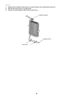
1. Remove the hex head screws holding the control to the cabinet.
2. Unplug the connectors from the cabinet harness and remove the control assembly.
3. Remove the cover of the board by squeezing the tabs on the cover to release the cover from the
assembly to expose the electronic control.
4. Unplug the wires from the electronic control board and unclip it from the control assembly.
Summary of Contents for RX256DT4X1
Page 11: ...321023 11 2 3 Refrigerant Flow...
Page 12: ...321023 12 2 4 Cabinet Air Flow...
Page 13: ...321023 13 2 5 Ice And Water Dispenser Diagram...
Page 14: ...321023 14 2 6 Water Valve Diagram...
Page 15: ...321023 15 2 7 Typical External Sweat Pattern...
Page 16: ...321023 16 3 INSTALLATION...
Page 17: ...321023 17...
Page 18: ...321023 18...
Page 76: ...321023 76 Ice Water Dispensing Board...
Page 78: ...321023 78 Mid Electronic Specification Control RX256DT4X1 RX256ET2B1 RX256ET2W1...
Page 104: ...321023 104 14 WIRING DIAGRAMS 14 1 Wiring Schematic RX256DT7X1...
Page 105: ...321023 105 14 2 Wiring Diagram RX256DT7X1...
Page 106: ...321023 106 14 3 Wiring Schematic RX256DT4X1 RX256ET2B1 RX256ET2W1...
Page 107: ...321023 107 14 4 Wiring Diagram RX256DT4X1 RX256ET2B1 RX256ET2W1...
Page 108: ...321023 108 NOTES...


