321023
85
11.3.7 Condenser
Removal
NOTE:
The condenser is removed by laying the unit on its back, and requires at least two people to
carry out this procedure.
1. Remove the machine compartment hex screws.
2. Remove
the
cover.
3. Remove the condenser fan motor and shroud.
4. Disconnect the harness plug connecting the machine compartment to the cabinet.
5. Follow reclaiming procedures in Section 13 of this manual.
6. Remove the drier and unbraze the tubing connecting the machine compartment to the cabinet.
7. Disconnect all cabinet wiring from the machine tray.
8. With the help of second person, lay the unit on its back on a raised surface.
9. Remove the four torx head screws holding the base pan to the cabinet.
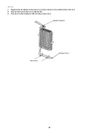
10. Lift and remove the base pan to access the condenser coil.
11. Unbraze the condenser coil from the connecting tubing.
12. Remove the condenser coil by unsnapping it from retainers in the base pan.
13. Reverse the procedure to reassemble.
11.4 Bottom
of
Cabinet
11.4.1
Front Levelling Rollers
1. Remove the toe grill and hinge caps.
2. Raise and block the unit up 75mm off the floor.
3. Screw the front leveller bolts until they are loose from the levelling roller.
4. Slide the levelling roller out the rear of the slot to remove the roller.
5. Reverse the procedure to reassemble.
11.4.2
Rear Levelling Rollers
1. Remove the machine compartment and water valve cover hex screws.
2. Remove
the
covers.
3. Tilt the unit forward lifting the rear of unit up about 75mm.
4. Block the unit up to keep weight off the rear levelling rollers.
5. Unscrew the levelling bolts from the rear levelling rollers.
6. Push the levelling roller out the slots in the bottom of the unit.
7. Reverse the procedure to reassemble.
11.5 Cabinet
Doors
11.5.1 Door
Gaskets
1. Grasp the gasket in the upper corners and pull the gasket out of the dart retainer.
2. When reinstalling the door gaskets, start at the corners, pushing the dart edge into the retainer and
make sure to seat the gasket flush to the door.
11.5.2 Dispenser
Façade
1. Remove the drip tray by pulling it straight out from the door.
2. Remove the two hex screws at the bottom of the façade that were hidden by the drip tray.
3. Push down on the façade to release the retainer clips.
4. Remove the façade and disconnect the ten-pin connector from the control board.
5. Reverse the procedure to reassemble.
Summary of Contents for RX256DT4X1
Page 11: ...321023 11 2 3 Refrigerant Flow...
Page 12: ...321023 12 2 4 Cabinet Air Flow...
Page 13: ...321023 13 2 5 Ice And Water Dispenser Diagram...
Page 14: ...321023 14 2 6 Water Valve Diagram...
Page 15: ...321023 15 2 7 Typical External Sweat Pattern...
Page 16: ...321023 16 3 INSTALLATION...
Page 17: ...321023 17...
Page 18: ...321023 18...
Page 76: ...321023 76 Ice Water Dispensing Board...
Page 78: ...321023 78 Mid Electronic Specification Control RX256DT4X1 RX256ET2B1 RX256ET2W1...
Page 104: ...321023 104 14 WIRING DIAGRAMS 14 1 Wiring Schematic RX256DT7X1...
Page 105: ...321023 105 14 2 Wiring Diagram RX256DT7X1...
Page 106: ...321023 106 14 3 Wiring Schematic RX256DT4X1 RX256ET2B1 RX256ET2W1...
Page 107: ...321023 107 14 4 Wiring Diagram RX256DT4X1 RX256ET2B1 RX256ET2W1...
Page 108: ...321023 108 NOTES...


