321023
9
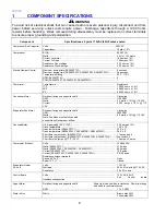
Light Switch (RX256DT4X1,
RX256ET2B1,
RX256ET2W1)
Type ............................................................................................................... SPST
NC
Volts ............................................................................................................... 125/250
VAC
Current ........................................................................................................... 8/4
amps
Light Switch / Interlock
Type ............................................................................................................... SPDT
NO/NC
Volts ............................................................................................................... 125/250
VAC
Current ........................................................................................................... 8/4
amps
Solenoid (Ice Chute)
Resistance across leads ................................................................................ 101 ohms ± 10%
Ice Maker Harvest
4 lbs of ice per 24 hours.
No-Load Performance, Controls in Normal Position
Kw/24 hr ±0.4
Percent Run Time
±10%
Cycles/24 hr
±25%
Provision Center
Compartment
Average Food
Temperature ±3°F
Freezer Compartment
Average Food
Temperature ±3°F
Ambient °F
70° 90° 110° 70° 90° 110° 70° 90° 110° 70° 90° 110°
70° 90° 110°
26cuft
1.2 1.85 2.6
35 55 75 24 24 19 37 39 42
0 0 -2
Temperature Relationship Test Chart
Evaporator Outlet
±3°F
Evaporator Inlet
±3°F
Suction Line
±7°F
Average Total
Wattage ±10%
Suction Pressure
±2 PSIG
Head Pressure
± 5 PSIG
Ambient °F
70° 90°
70° 90° 70° 90° 70° 90°
70° 90°
70° 90°
26cuft
-15 -15
-16 -16
72 98
132 138
6"(Vac.) 0
87 137
2 PRODUCT
DESIGN
2.1 Refrigeration
System
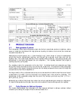
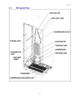
The compressor forces high temperature vapor into the fan cooled tube and wire condenser, where
vapor is cooled and condensed into high pressure liquid by circulation of air across the condenser
coil (refer to Section 2.3).
High-pressure liquid passes into a post-condenser loop, which helps to prevent condensation
around the freezer compartment opening, and through the molecular sieve drier and into the
capillary tube. The small inside diameter of the capillary offers resistance, decreasing pressure and
temperature of the liquid discharged into the evaporator. The capillary diameter and length is
carefully sized for each system.
The capillary enters the evaporator at the top front. Combined liquid and saturated gas flows
through the front to the bottom of the coil and into the suction line. The aluminium tube evaporator
coil is located in the freezer compartment where the circulating evaporator fan moves air through the
coil and into the fresh food compartment.
The large surface of the evaporator allows heat to be absorbed from both the fresh food and freezer
compartments, by airflow over the evaporator coil causing some of the liquid to evaporate. The
temperature of the evaporator tubing near the end of the running cycle may vary from –13
O
F to –
25
O
F (-25
O
C to –31
O
C).
Saturated gas is drawn off through the suction line, where superheated gas enters the compressor.
To raise the temperature of the
gas, the suction line is placed in heat exchange with the capillary.
2.2
Fully Electronic Defrost System
The Control Board adapts the compressor run time between defrosts to achieve optimum defrost
intervals by monitoring the length of time the defrost heater is on.
Summary of Contents for RX256DT4X1
Page 11: ...321023 11 2 3 Refrigerant Flow...
Page 12: ...321023 12 2 4 Cabinet Air Flow...
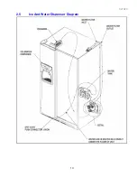
Page 13: ...321023 13 2 5 Ice And Water Dispenser Diagram...
Page 14: ...321023 14 2 6 Water Valve Diagram...
Page 15: ...321023 15 2 7 Typical External Sweat Pattern...
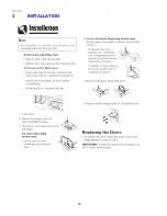
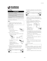
Page 16: ...321023 16 3 INSTALLATION...
Page 17: ...321023 17...
Page 18: ...321023 18...
Page 76: ...321023 76 Ice Water Dispensing Board...
Page 78: ...321023 78 Mid Electronic Specification Control RX256DT4X1 RX256ET2B1 RX256ET2W1...
Page 104: ...321023 104 14 WIRING DIAGRAMS 14 1 Wiring Schematic RX256DT7X1...
Page 105: ...321023 105 14 2 Wiring Diagram RX256DT7X1...
Page 106: ...321023 106 14 3 Wiring Schematic RX256DT4X1 RX256ET2B1 RX256ET2W1...
Page 107: ...321023 107 14 4 Wiring Diagram RX256DT4X1 RX256ET2B1 RX256ET2W1...
Page 108: ...321023 108 NOTES...


