- 38 -
5.2.6
Check the Flame Detector (Gas Only)
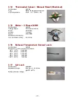
The flame detector is much like a thermostat, although it is sensitive to radiant heat
whereas a thermostat relies more on conduction/convection to get hot. However
they are both essentially just switches. Therefore when it is cold the sensor should
be closed circuit (near zero resistance) and when the sensor is sufficiently hot the
switch will open (open circuit). Because it senses radiant heat, a temperature for
switching is not specified.
To test it, run the dryer and see if the flame detector goes open circuit after the igniter
has been on for a while (40-60 seconds depending on the voltage and air flow). It
should stay open circuit while the gas is burning and then cool down and close after
the gas flame goes out (about 30 seconds depending on the airflow and air temp).
5.2.7
Check the Igniter (Gas Only)
(a)
Disconnect the igniter and measure the resistance. Resistance should be
between 40 and 200 ohms when cold.
5.2.8
Check the Exhaust Sensor (Gas and Electric)
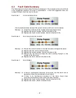
This check will need to be performed if the dryer has stopped functioning and fault
codes 8 or 9 have been displayed.
(a)
Disconnect the temperature sensor from the sensor module and measure the
resistance. Resistance at various ambient temperatures should be (+/- 10%):
32ºF (0ºC)
= 33 kOhm
(+10%)
50ºF (10ºC)
= 20 kOhm (+10%)
68ºF (20ºC)
= 12 kOhm (+10%)
86ºF (30ºC)
=
8 kOhm (+10%)
104ºF (40ºC)
=
5 kOhm (+10%)
(b)
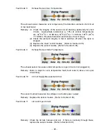
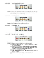
If the sensor resistance checks out correct, refer to Fault Codes in Section 4.2.
5.2.9
Check Inlet and Outlet Duct Seals
If the seals are faulty, replace. (Refer to Sections 6.26 and 6.20)
5.3
Problem – Drum Does Not Rotate
The following checks are based on the control panel LEDs lighting up when the
Power
button is pressed, but no drum rotation when
Start/Pause
is pressed. Note: The lid must
be closed or else a warning sound will be given.
5.3.1
Check for Fault Code.
If a fault code is present, follow the instructions in Section 4.2.
5.3.2
Check the Integrity of the Belt.
(a) Follow instructions for removal of components within cabinet. (Refer to Section
6.6)
(b) Check that the belt is intact and in place. If not, follow instructions for removal
and replacement of the belt. (Refer to Section 6.29)
Summary of Contents for Smartload DEGX1
Page 1: ...DRYER Models DEGX1 DGGX1 517760 ...
Page 2: ......
Page 60: ... 60 7 Wiring Diagrams 7 1 U S A Model Electric ...
Page 61: ... 61 7 2 U S A Model Gas ...
Page 69: ... 69 Notes ...

