- 45 -
Reassembly
(a) Refit in reverse manner.
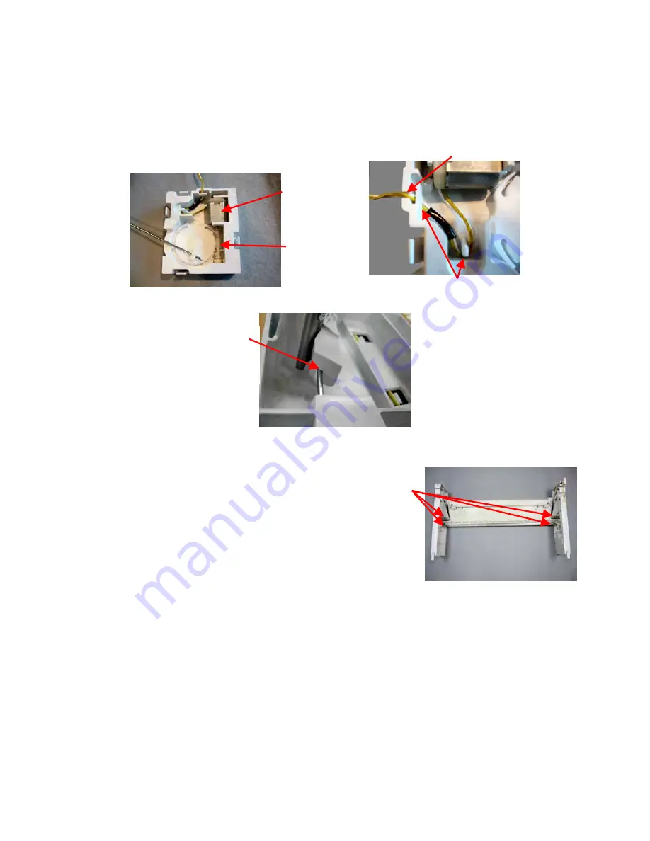
(b) Ensure that the wiring to the actuator motor is clipped under the hooks and is in the
slots in the cover.
(c) With the actuator clipped into the grabber housing, ensure that the actuator linkage is
located correctly. There must be no gap between the linkage and the plastic
moulding of the housing.
6.10 Removal of Door Grabber
(a) Follow instructions for removal of the door grabber
actuator assembly. (Refer to Section 6.9)
(b) Remove the four screws securing the chassis beam
to the grabber housings.
(c) Lift the door grabber clear.
Reassembly
(a) Refit in reverse manner. Ensure that the linkage is
correctly located in the slot of the door grabber.
No gap between
linkage and
moulding at this
point
Wiring in slot
Clipped under hooks
Motor in place
Worm drive
can rotate
freely
Summary of Contents for Smartload DEGX1
Page 1: ...DRYER Models DEGX1 DGGX1 517760 ...
Page 2: ......
Page 60: ... 60 7 Wiring Diagrams 7 1 U S A Model Electric ...
Page 61: ... 61 7 2 U S A Model Gas ...
Page 69: ... 69 Notes ...

