Lit. No. 49591, Rev. 05
6
July 15, 2020
27775, 28069, 57000, 57000‑1, 57000‑3
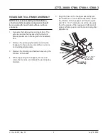
5.
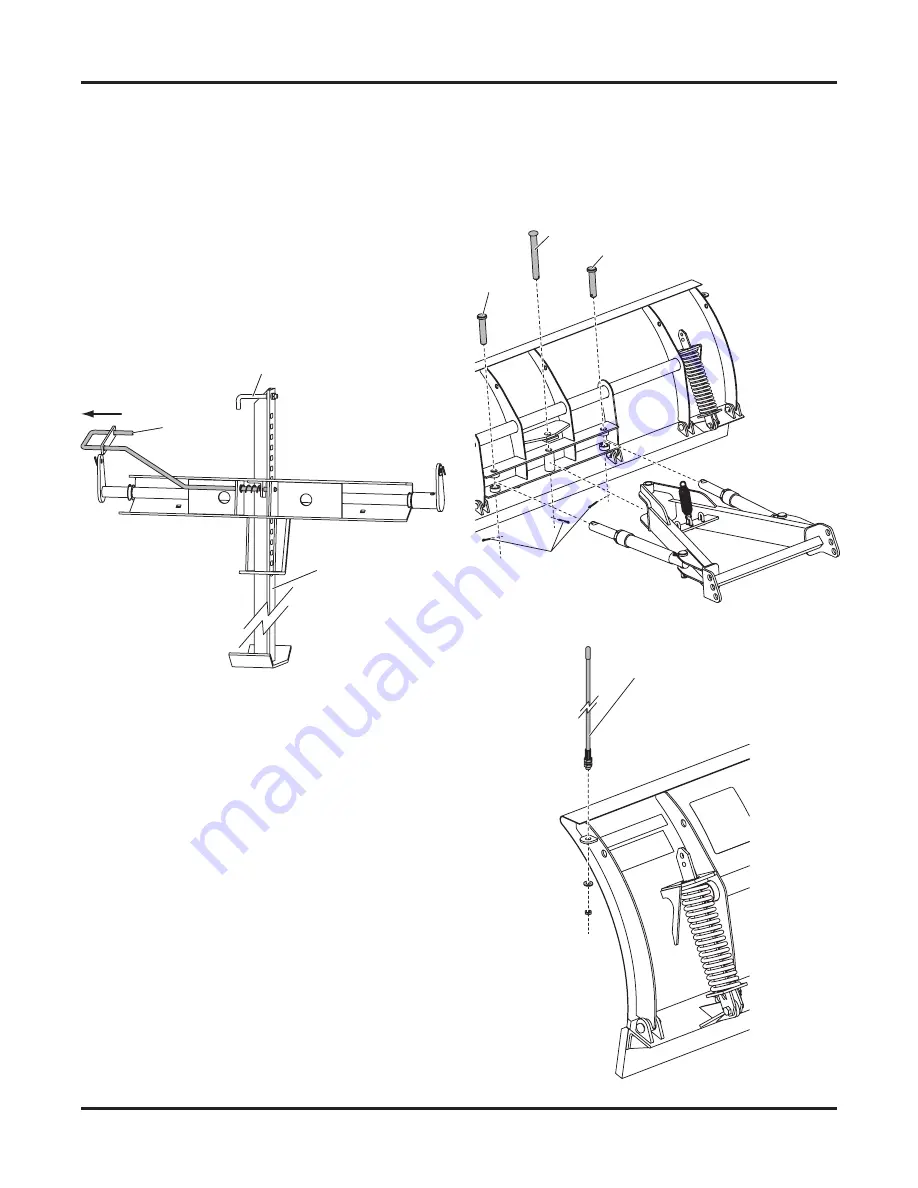
Align the angle ram rods with the angle ram
holes on the blade, and attach using two
1" x 4‑3/4" clevis pins, installed from the top.
Secure with 1/4" x 1‑1/2" cotter pins.
6.
Install the blade guides.
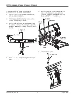
A‑FRAME TO BLADE ASSEMBLY
1.
Align the pivot‑pin hole on the A‑frame with the
pivot‑pin hole on the blade.
2.
Install the pivot pin from the top. Secure with a
1/4" x 2" cotter pin at the bottom.
3.
With the blade in normal operating position, pull
the jack lock and lower the jack leg to support the
headgear. Release the jack lock to hold the jack in
position.
4.
Remove the protective packaging from the angle
rams.
Headgear
not shown.
Pivot Pin
Clevis
Pin
Cotter
Pins
Clevis Pin
Jack Handle
Jack Lock
Jack
Blade Guide


