background image

167D Series

6

       the lines or from external sources.  Switching     

       valves should be inspected for damage  


       periodically and after any overpressure condition.

  2.  Only personnel qualified through training and  

       experience should install, operate, and maintain 

       a switching valve.  Make sure that there is no  

       damage to or foreign material in the switching  

       valve.  Also ensure that all tubing and piping is 

       free of debris.

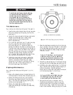
  3.  Install the switching valve to achieve the desired  

       switching results.  Connect the control pressure  

       line to either D port.  Verify that the other D port  

       is plugged.  The port labeled “IN” or port A is the 


       common inlet connection and ports B and C are  

       the outlet connections.  Flow is either from A to B 


       or A to C.
  4.  A clogged spring case vent hole may cause the  

       switching valve to function improperly.  To keep  

       this vent hole from being plugged (and to keep  

       the spring case from collecting moisture, corrosive  

       chemicals, or other foreign material) orient the  

       vent to the lowest possible point on the spring    

       case or otherwise protect it. 
       Inspect the vent hole regularly to make  


       sure it is not plugged.  Spring case vent  


       hole orientation may be changed by rotating the  

       spring case with respect to the body.  A 1/4 NPT  

       spring case vent may be remotely vented by  

       installing obstruction-free tubing or piping into   

       the vent.  Protect the remote vent by installing a  

       screened vent cap on the remote end of the 

       vent pipe.       
  5.  For use in switching valve shutdown, install     

       upstream block and vent valves and downstream 

       block and vent valves (if required), or provide 

       some other suitable means of properly venting the 

       switching valves inlet and outlet pressures.  Install 

       a pressure gauge to monitor instruments 

       on startup.    

  6.  Apply a good grade of pipe compound to the

       external pipe threads before making connections,

       making sure not to get the pipe compound inside 

       the switching valves.

  7.  Install tubing fitting or piping into the threaded NPT

       inlet connection on the body (key 1) and into the

        threaded NPT outlet connections.

  8.  The 1/4 NPT control pressure ports must be 

       plugged if not in use. 

Startup and Adjustment

Key numbers are referenced in Figures 7 through 13.

  1.  With proper installation completed and downstream  

        equipment properly adjusted, slowly open the  

       upstream and downstream shut-off valve (when 

       used) while using pressure gauges to 

       monitor pressure.

!

WARNING

 To avoid personal injury, property 

damage, or equipment damage caused   

by bursting of pressure containing parts 

or explosion of accumulated gas, never 

adjust the control spring to produce an 

outlet pressure higher than the upper 

limit of the outlet pressure range for that 

particular spring.  If the desired outlet 

pressure is not within the range of the 

control spring, install a spring of the 

proper range according to the diaphragm 

parts maintenance procedure.

  2.  If outlet pressure adjustment is necessary, 

       monitor outlet pressure with a gauge during the 

       adjustment  procedure.  The switching valve 

       is adjusted by loosening the hexnut (key 19), 

       if used, and turning the adjusting screw or  

        handwheel (key 18) clockwise to increase or  

       counterclockwise to decrease the outlet pressure  

       setting.  Retighten the hexnut to maintain the 

       adjustment position.


Maintenance

Switching valve parts are subject to normal wear and 

must be inspected and replaced as necessary.  The 

frequency of inspection and replacement of parts 

depend on the severity of service conditions and 

applicable codes and government regulations.  


Note

If sufficient clearance exists, the body 

(key 1) may remain mounted on other 

equipment or in a line or panel during 

maintenance unless the entire switching  

valve will be replaced.

Summary of Contents for 167D

Page 1: ...hnologies Inc instructions If the switching valve vents gas or a leak develops in the system service to the unit may be required Failure to correct trouble could result in a hazardous condition Installation operation and maintenance procedures performed by unqualified personnel may result in improper adjustment and unsafe operation Either condition may result in equipment damage or personal injury...

Page 2: ...ns Types 167D and 167DA Handwheel adjusting screw Fluorocarbon FKM diaphragm soft seat seat and O rings Stainless steel valve stem and plug Includes stainless steel seat 1 hole panel mount with handwheel adjusting screw and 1 4 NPT tap spring case 3 hole panel mount bonnet with handwheel adjusting screw and 1 4 NPT spring case 1 4 NPT tapped vent spring case 1 4 NPT tapped vent and closing cap Adj...

Page 3: ... 35 0 97 to 1 4 1 1 to 2 4 7 to 20 10 to 30 0 48 to 1 4 0 69 to 2 1 White stripe Purple stripe Zinc plated Music Wire GE40282X012 GE40283X012 0 145 0 156 3 68 3 96 1 425 36 2 10 13 0 69 0 90 25 to 60 40 to 125 1 7 to 4 1 2 8 to 8 6 25 to 50 40 to 90 1 7 to 3 4 2 8 to 6 2 Brown stripe Pink stripe Chrome Silicon GE40284X012 GE40345X012 0 172 0 207 4 37 5 26 17 35 1 2 2 4 167DAS 14 to 20 16 to 35 25 ...

Page 4: ...ceed the maximum outlet pressure rating Overpressuring any portion of a switching valve or associated equipment may cause leakage parts damage or personal injury due to bursting of pressure containing parts or explosion of accumulated gas Switching valve operation within ratings does not preclude the possibility of damage from external sources or from debris in the pipeline A switching valve shoul...

Page 5: ...RE GAUGE Figure 3 Typical 167DA or 167DAS Installation Lockup system using Type 167DA or 167DAS to close air circuit to diaphragm of main valve in case of plant air failure Main valve will remain in position it occupied at time of supply pressure failure TYPE 657 TYPE 67CFR TYPE DVC6010 TYPE 167DA OR 167DAS 1 4 NPT SUPPLY A B A B C D 10C0622 TYPE 657 TYPE DVC6010 67CFR CHECK VALVE 1 4 NPT 3 4 NPT ...

Page 6: ... grade of pipe compound to the external pipe threads before making connections making sure not to get the pipe compound inside the switching valves 7 Install tubing fitting or piping into the threaded NPT inlet connection on the body key 1 and into the threaded NPT outlet connections 8 The 1 4 NPT control pressure ports must be plugged if not in use Startup and Adjustment Key numbers are reference...

Page 7: ...tenance Key numbers are referenced in Figures 7 through 10 1 Unscrew the spring retainer key 48 and separate the spring retainer and O ring key 14 from the body key 1 2 Inspect the removed parts for damage and debris Replace any damaged parts Apply a high quality lubricant to the O ring key 50 before reassembling 3 To remove the valve stem key 11 and valve plug key 57 grasp the end and pull it str...

Page 8: ...s Steel GE35519X032 Types 167DS and 167DAS 316L Stainless steel GE35519X032 Key Description Part Number 12 Valve Spring Type 167D or 167DS 302 Stainless steel GE31783X012 Inconel X 750 NACE GG00430X012 Type 167DA or 167DAS 302 Stainless steel ERAA00153A0 Inconel X 750 NACE ERAA00154A0 14 O ring Spring Retainer Nitrile NBR 10A3803X092 Fluorocarbon FKM 10A3803X112 15 Soft Seat Types 167D and 167DS o...

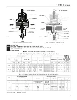
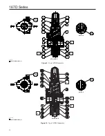
Page 9: ... Type 167D Assembly 18 19 20 17 15 50 14 57 7 16 3 50 11 58 1 48 12 A APPLY LUBBRICANT L GE37632 Figure 8 Type 167DA Assembly SECTION B B GF02289_B APPLY LUBBRICANT L DETAIL A DETAIL A B B SECTION B B B B L L L L L L L L L L ...

Page 10: ...Type 167DS Assembly 18 19 20 17 45 1 16 15 11 50 12 33 7 3 50 58 57 14 48 A APPLY LUBRICANT L Figure 10 Type 167DAS Assembly L APPLY LUBRICANT L GE37724 GE37725_B DETAIL A DETAIL A SECTION B B SECTION B B B B B B L L L L L L L ...

Page 11: ...Available with the 1 4 NPT Spring Case Vent Figure 12 Types 167D and 167DS Diaphragm Assembly Key 16 B2696 RETAINING RING LOWER SPRING SEAT DIAPHRAGM HEAD PUSHER POST WITH RELIEF DIAPHRAGM 33 18 19 GE37632 Figure 11 Optional Panel Mount GE37632 18 19 31 ...

Page 12: ... 800 558 5853 Outside U S 1 972 548 3574 Asia Pacific Singapore 128461 Singapore Tel 65 6777 8211 Europe Bologna 40013 Italy Tel 39 051 419 0611 Gallardon 28320 France Tel 33 2 37 33 47 00 TESCOM Emerson Process Management Tescom Corporation USA Headquarters Elk River Minnesota 55330 2445 USA Tels 1 763 241 3238 1 800 447 1250 Europe Selmsdorf 23923 Germany Tel 49 38823 31 287 Asia Pacific Shangha...

Reviews: