C1 Controllers and Transmitters
Instruction Manual
September 2009
8
If operating the controller or transmitter from a high
pressure source [up to 138 bar (2000 psig)], use a
high pressure regulator system, such as the Fisher
1367 High Pressure Instrument Supply System. For
1367 system installation, adjustment, and
maintenance information, refer to the 1367
High
−
Pressure Instrument Supply System with
Overpressure Protection instruction manual,
D100343X012.
Process Pressure
WARNING
To avoid personal injury or property
damage resulting from the sudden
release of pressure when using
corrosive media, make sure the tubing
and instrument components that
contact the corrosive medium are of
suitable noncorrosive material.
Also refer to the Installation Warning
at the beginning of this section.
The pressure connections to the controller depend
upon the type of pressure sensing, gauge or
differential. Gauge pressure controllers use either a
Bourdon tube or bellows as the sensing element, as
indicated in table 2. Differential pressure controllers
use two bellows to sense differential pressure.
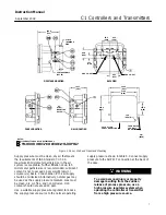
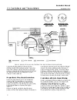
For gauge pressure instruments: The control
pressure block (key 10 in figure 21) has two
connections. Process pressure can be connected
either to the CONTROL connection on the back of
the case, or to the connection on the left side of the
case, shown in figure 2, depending on the
instrument application. Plug the unused connection.
For differential pressure instruments: Connect
the low pressure line to the CONTROL connection
on the side of the case and the high pressure line to
the CONTROL connection on the back of the case
as shown in figure 2.
When installing process piping, follow accepted
practices to ensure accurate transmission of the
process pressure to the controller or transmitter.
Install shutoff valves, vents, drains, or seal systems
as needed in the process pressure lines. If the
instrument is located such that the adjacent process
pressure lines will be approximately horizontal, the
lines should slope downward to the instrument for
liquid
−
filled lines and upward to instruments for
gas
−
filled lines. This will minimize the possibility of
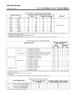
Table 6. Common Signal Pressure Conversions
Mps
kg/cm
2
bar
kPa
Psi
0.02
0.03
0.04
0.05
0.06
0.2
0.3
0.4
0.5
0.6
0.2
0.3
0.4
0.5
0.6
20
35
40
50
60
3
5
6
7
9
0.07
0.08
0.09
0.10
0.12
0.8
0.8
1.0
1.0
1.3
0.8
0.8
1.0
1.0
1.2
75
80
95
100
125
11
12
14
15
18
0.14
0.15
0.17
0.18
0.20
1.4
1.5
1.8
1.9
2.0
1.4
1.5
1.7
1.9
2.0
140
150
170
185
200
20
22
25
27
30
0.22
0.23
0.24
0.34
0.55
2.2
2.3
2.5
3.5
5.6
2.2
2.3
2.4
3.4
5.5
220
230
240
345
550
32
33
35
50
80
0.69
1.03
7.0
10.5
6.9
10.3
690
1035
100
150
1. Values as listed in ANSI/S7.4.
2. Values as listed in IEC Standard 382.
3. Values rounded to correspond with kPa values.
air becoming trapped in the sensor with liquid
−
filled
lines or of condensation becoming trapped with
gas
−
filled lines. The recommended slope is 83 mm
per meter (1 inch per foot).
If a controller is being used in conjunction with a
control valve to control pipeline pressure, connect
the process pressure line in a straight section of pipe
approximately 10 pipe diameters from the valve but
away from bends, elbows, and areas of abnormal
fluid velocities. For pressure
−
reducing service, the
process line must be connected downstream of the
valve. For pressure
−
relief service, the process
pressure line must be connected upstream of the
control valve. Install a needle valve in the process
pressure line to dampen pulsations.
Vent Assembly
WARNING
Personal injury or property damage
could result from fire or explosion of
accumulated gas, or from contact with
hazardous gas, if a flammable or
hazardous gas is used as the supply
pressure medium. Because the
instrument case and cover assembly
do not form a gas
−
tight seal when the
assembly is enclosed, a remote vent


