background image

www.Fisher.com

Fisher

r

 EHD and EHT NPS 8 through 14

Sliding-Stem Control Valves

Contents

Introduction

1

. . . . . . . . . . . . . . . . . . . . . . . . . . . . . . . 

Scope of Manual

1

. . . . . . . . . . . . . . . . . . . . . . . . . . 

Description

2

. . . . . . . . . . . . . . . . . . . . . . . . . . . . . . . 

Specifications

2

. . . . . . . . . . . . . . . . . . . . . . . . . . . . 

Installation

3

. . . . . . . . . . . . . . . . . . . . . . . . . . . . . . . . 

Principle of Operation

4

. . . . . . . . . . . . . . . . . . . . . . . 

Maintenance

4

. . . . . . . . . . . . . . . . . . . . . . . . . . . . . . 

Packing Lubrication

5

. . . . . . . . . . . . . . . . . . . . . . . 

Packing Maintenance

6

. . . . . . . . . . . . . . . . . . . . . . 

Replacing Packing

6

. . . . . . . . . . . . . . . . . . . . . . . 

Trim Removal

10

. . . . . . . . . . . . . . . . . . . . . . . . . . . 

EHD, EHT Valve Plug Maintenance

10

. . . . . . . . 

Lapping Seats

11

. . . . . . . . . . . . . . . . . . . . . . . . . . . 

Trim Replacement

11

. . . . . . . . . . . . . . . . . . . . . . . 

Retrofit: Installing Bore Seal Trim

13

. . . . . . . . . . . 

Replacement of Installed Bore Seal Trim

15

. . . . 

Trim Removal (Bore Seal Constructions)

15

. . . 

Lapping Metal Seats 

(Bore Seal Constructions)

16

. . . . . . . . . . . . . 

Remachining Metal Seats

(Bore Seal Constructions)

16

. . . . . . . . . . . . . 

Trim Replacement 

(Bore Seal Constructions)

17

. . . . . . . . . . . . . 

Actuator Mounting

18

. . . . . . . . . . . . . . . . . . . . . . . 

Parts Ordering

18

. . . . . . . . . . . . . . . . . . . . . . . . . . . . 

Parts Kits

19

. . . . . . . . . . . . . . . . . . . . . . . . . . . . . . . . 

Parts List

21

. . . . . . . . . . . . . . . . . . . . . . . . . . . . . . . . 

Bonnet Assembly

21

. . . . . . . . . . . . . . . . . . . . . . . . 

Valve Assembly

23

. . . . . . . . . . . . . . . . . . . . . . . . . 

Introduction

Scope of Manual

This instruction manual includes installation,
maintenance, and parts ordering information for 
NPS 8 through 14 Fisher

r

 EHD and EHT

sliding-stem globe-style control valves. Refer to
separate manuals for instructions covering the
actuator, positioner, and accessories.

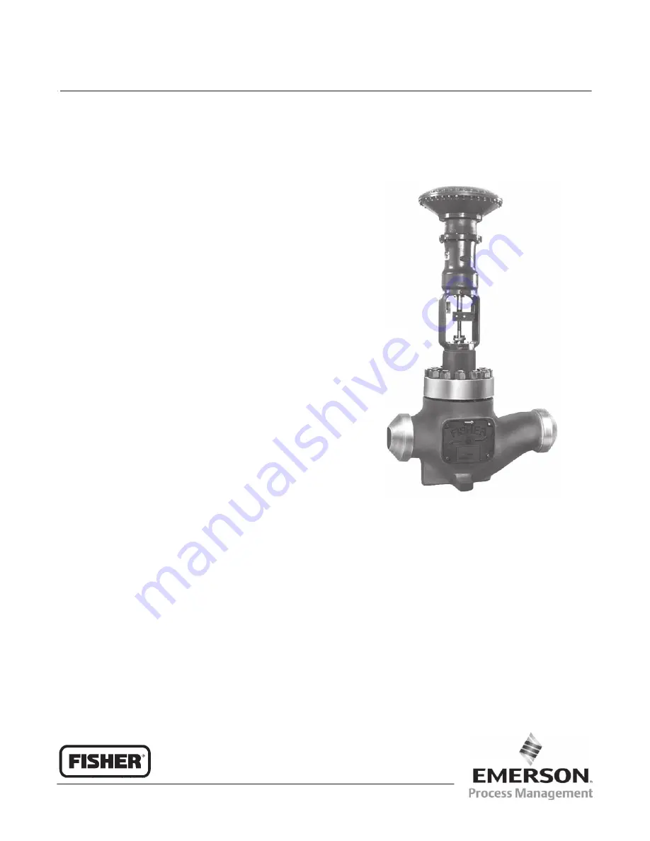
Figure 1. Fisher

r

 EH Series Control Valve 

with 667 Actuator

W2992-1/IL

Do not install, operate, or maintain an EH valve
without being fully trained and qualified in valve,
actuator, and accessory installation, operation, and
maintenance. To avoid personal injury or property
damage, it is important to carefully read, understand,
and follow all the contents of this manual, including
all safety cautions and warnings. If you have any
questions about these instructions, contact your
Emerson Process Management sales office before
proceeding.

Instruction Manual

D100392X012
April 2009

EH Valves (NPS 8 through 14)

Summary of Contents for EHD

Page 1: ...1 Valve Assembly 23 Introduction Scope of Manual This instruction manual includes installation maintenance and parts ordering information for NPS 8 through 14 Fisherr EHD and EHT sliding stem globe style control valves Refer to separate manuals for instructions covering the actuator positioner and accessories Figure 1 Fisherr EH Series Control Valve with 667 Actuator W2992 1 IL Do not install oper...

Page 2: ...es using an equal percentage cage may be travelled an additional 13 mm 0 5 inch if desired to obtain additional capacity flow characteristic becomes modified equal percentage Table 2 Shutoff Classifications 1 VALVE DESIGN ANSI FCI LEAKAGE CLASS EHD III Standard IV Optional EHT IV Standard V Optional EHT w PEEK 2 Anti Extrusion Rings V to 316_C 600_F 1 Per ANSI FCI 70 2 and IEC 60534 4 2 Poly Ether...

Page 3: ...ould exceed the limits given in this manual or on the appropriate nameplates Use pressure relieving devices as required by government or accepted industry codes and good engineering practices Check with your process or safety engineer for any additional measures that must be taken to protect against process media If installing into an existing application also refer to the WARNING at the beginning...

Page 4: ...sult from packing leakage Valve packing was tightened prior to shipment however some readjustment will be required to meet specific service conditions 7 If the valve was shipped without packing installed in the packing box install the packing prior to putting the valve into service Refer to instructions given in the Packing Maintenance section of this manual Principle of Operation Key numbers refe...

Page 5: ...s install a new gasket upon reassembly This is necessary to ensure a good gasket seal 8 After all maintenance is complete refer to the Trim Replacement procedure to assemble the valve body Note If the valve has ENVIRO SEALr live loaded packing installed see the Fisher instruction manual titled ENVIRO SEAL Packing System for Figure 2 Lubricator and Lubricator Isolating Valve LUBRICATOR LUBRICATOR I...

Page 6: ...s key 5 figure 11 to at least the minimum recommended torque in table 5 However do not exceed the maximum recommended torque in table 5 or excessive friction may result Table 5 Recommended Packing Flange Nut Torques STEM DIAMETER VALVE RATING NSm LbfSft mm Inches Min Max Min Max 31 8 1 1 4 CL1500 68 102 50 75 CL2500 81 122 60 90 50 8 2 CL1500 98 146 72 108 CL2500 115 170 85 125 If the packing is r...

Page 7: ... figure 12 or 13 This avoids damage to the seating surfaces as a result of the assembly dropping from the bonnet after being lifted part way out The parts are also easier to handle separately 4 Remove the hex nuts key 14 figure 12 or 13 and washers key 29 figure 12 or 13 Carefully lift Figure 3 Actuator Mounting ANTI ROTATION GROOVE TRAVEL INDICATOR STEM CONNECTOR POINTER STEM LOCKNUTS MOUNTING ST...

Page 8: ...MENT PACKING RING KEY 9 LANTERN RING KEY 8 PACKING BOX RING KEY 11 3 PACKING FOLLOWER KEY 13 PACKING RING KEY 7 LANTERN RING KEY 8 PACKING BOX RING KEY 11 12A7839 A IL Sht 1 14A3414 B IL 12A8163 A IL PTFE V RING DOUBLE PACKING GRAPHITE LAMINATE AND FILAMENT DOUBLE PACKING PTFE COMPOSITION DOUBLE PACKING UPPER WIPER KEY 12 PACKING FOLLOWER KEY 13 PACKING RING KEY 7 LANTERN RING KEY 8 PACKING BOX RI...

Page 9: ...nnet to body bolting practices and the torque values shown in table 6 may result in cage crushing cage diameter reduction and or bonnet deformation Do not use cheater bars or slug wrenches for this procedure Hot torquing is not recommended it may result in damage to valve components 13 Lubricate the stud threads and the faces of the hex nuts key 14 figure 12 or 13 with anti seize lubricant not nec...

Page 10: ...alve Use the eyebolts to carefully lift the seat ring out of the valve body If the seat ring is to be reused exercise care to protect the gasket surfaces on the bottom of the seat ring 3 Remove the spiral wound seat ring gasket or O ring key 12 4 Refer to the following appropriate valve plug maintenance procedure or to the Lapping Seats procedure EHD and EHT Valve Plug Maintenance Key numbers used...

Page 11: ...p the seats Note In order to preserve the effects of lapping do not change either the position of the seat ring in the valve body cavity or the position of the cage on the seat ring after lapping the seating surfaces If possible clean the parts without disturbing their positions If the parts must be removed for cleaning return them to the original positions 5 After lapping again disassemble as nec...

Page 12: ... cage 7 Install the other cage gasket key 11 between the cage and the bonnet CAUTION Failure to comply with good bonnet to body bolting practices and the torque values shown in table 6 may result in cage crushing cage diameter reduction and or bonnet deformation Cheater bars or slug wrenches should not be used for this procedure Hot torquing is not recommended it may result in damage to valve comp...

Page 13: ...office for assistance in determining new actuator thrust requirements Assemble the new valve plug retainer assembly with Bore Seal plug seal using the following instructions CAUTION To avoid leakage when the valve is returned to service use appropriate methods and materials to protect all sealing surfaces of the new trim parts while assembling the individual parts and during installation in the va...

Page 14: ...t the Bore Seal plug seal for correct sealing action based on the process fluid flow direction through the valve D The open interior of the Bore Seal plug seal must face up in a valve with flow up construction figure 5 D The open interior of the Bore Seal plug seal must face down in a valve with flow down construction figure 5 Note An installation tool must be used to properly position the Bore Se...

Page 15: ...ce calculated for full load when sizing your actuator With no pressure drop across the valve this force will adequately drive the valve plug to the seat ring thus giving the Bore Seal plug seal a predetermined permanent set Once this is done the plug retainer assembly the cage and the seat ring become a matched set With full actuator force applied and the valve plug fully seated align the actuator...

Page 16: ...gure 9 8 Inspect the lower seating surface where the valve plug contacts the seat ring for wear or damage which would prevent proper operation of the valve Also inspect the upper seating surface inside the cage where the Bore Seal plug seal contacts the Figure 8 Installing the Bore Seal Plug Seal Using the Installation Tool Bore Seal METAL PLUG SEAL INSTALLATION TOOL A6778 IL VALVE PLUG HORIZONTAL...

Page 17: ...s the Bore Seal plug seal onto the plug until the installation tool contacts the horizontal reference surface of the valve plug figure 8 4 Apply a suitable high temperature lubricant to the threads on the plug Then place the Bore Seal retainer onto the plug and tighten the retainer using an appropriate tool such as a strap wrench 5 Using an appropriate tool such as a center punch stake the threads...

Page 18: ... scale to the required position 8 Stroke the valve to the closed position The travel indicator should show the valve to be closed 9 If travel is not correct lift the valve plug assembly key 3 figure 12 or 13 off its seat approximately 6 4 mm 1 4 inch and screw the valve plug stem into or out of the stem connector as follows To lengthen travel turn the valve plug stem into the stem connector slight...

Page 19: ...ecifications may adversely alter the performance of the packing kit Stem Diameter mm Inches Yoke Boss Diameter mm Inches Kits Packing Material Double PTFE Graphite ULF Duplex 31 8 1 1 4 127 5 5H RPACKXRT052 RPACKXRT302 RPACKXRT252 ENVIRO SEALr Packing Repair Kits Repair kits include parts to replace the soft packing materials in valves that already have ENVIRO SEAL packing arrangements installed o...

Page 20: ...53 A A6297 1 IL Typical HIGH SEAL ULF Packing System Typical ENVIRO SEAL Packing System with PTFE Packing Typical ENVIRO SEAL Packing System with Graphite ULF Packing Typical ENVIRO SEAL Packing System with Duplex Packing 200 212 201 215 216 207 209 211 217 207 207 207 214 213 A6722 IL 39B4612 A ...

Page 21: ...Part Number 5 Packing Flange Nut 127 mm 5 inch yoke boss diameter 2 req d 178 mm 7 inch yoke boss diameter 3 req d 6 Packing Set See following table 7 Packing Ring See following table 8 Spring or Lantern Ring See following table 9 Packing Ring See following table 10 Washer See following table 11 Packing Box Ring See following table 12 Upper Wiper felt See following table 13 Packing Follower 316 st...

Page 22: ...nt single packing 7 9 Graphite Laminate Packing Rings Graphite Filament Packing Rings 3 4 10A4801X022 1N2600X0042 Low chloride graphite laminate and filament double packing 7 9 Graphite Laminate Packing Rings Graphite Filament Packing Rings 3 4 10A4801X022 1N2600X0042 Graphite composition double packing 7 Packing Rings 7 1N2600X0032 12 Upper Wiper 1 1V313206332 PTFE composition double packing 7 Pa...

Page 23: ...22 CL2500 15A4010X022 For valve with Whisper Trim III cage NPS 8 and 10 valves CL1500 15A4010X032 CL2500 15A3974X022 NPS 12 and 14 valves CL1500 15A3946X032 CL2500 15A4010X022 Key Description Part Number 9 Backup Ring for use only with EHT valve For valve with other than Whisper Trim III cage NPS 8 and 10 valves CL1500 316 stainless steel 15A4009X022 416 stainless steel 15A4009X012 CL2500 316 stai...

Page 24: ...L TRIMS EXCEPT THOSE WITH WHISPER TRIM III CAGES O RING CONSTRUCTION GASKET CONSTRUCTION VIEW A APPLY LUBRICANT 59A9171 A IL COMPLETE VALVE SHOWING VALVE PLUG WITHOUT DIVERTER CONE DIVERTER CONE DETAIL WHISPER TRIM LEVEL A B OR C DETAIL WHISPER TRIM LEVEL D DETAIL 59A9172 A C0632 1 IL 59A9180 A IL 59A9182 A IL ...

Page 25: ...IMS EXCEPT THOSE WITH WHISPER TRIM III CAGES O RING CONSTRUCTION GASKET CONSTRUCTION VIEW A APPLY LUBRICANT 59A9177 A IL COMPLETE VALVE SHOWING VALVE PLUG WITHOUT DIVERTER CONE DIVERTER CONE DETAIL WHISPER TRIM LEVEL A B OR C DETAIL WHISPER TRIM LEVEL D DETAIL 59A9184 A IL 59A9186 A IL 59A9178 A C0633 1 IL VIEW B ...

Page 26: ...D5470X0012 CL2500 Nitrile 19A9013X012 Ethylene propylene 19A9013X042 Fluorocarbon 19A9013X032 NPS 12 and 14 valves CL1500 Nitrile 19A9014X012 Ethylene propylene 19A9014X042 Fluorocarbon 19A9014X032 CL2500 Nitrile 1D5470X0032 Ethylene propylene 1D5470X0042 Fluorocarbon 1D5470X0012 Figure 14 Fisherr EHT Valve Using PEEK Anti Extrusion Rings FLOW UP FLOW DOWN A7220 IL Key Description Part Number 13 B...

Page 27: ...442X012 49A7443X012 39A7440X012 49A7443X012 49A7442X022 39A7439X022 49A7442X022 Key 2 Whisper Trimr III Cage VALVE SIZE NPS CAGE CONSTRUCTION Cr Ct M152 SST 17 4PH STAINLESS STEEL WITH H1150 DBL HEAT TREATMENT FOR SOUR GAS SERVICE CL1500 Rating CL2500 Rating CL1500 Rating CL2500 Rating 8 10 Level A1 Level A3 Level B1 Level B3 Level C1 Level C3 Level D1 1 Level D3 1 30B1118X012 30B1120X012 30B1122X...

Page 28: ...A7494X012 35A3970X012 39A7495X012 35A3971X012 39A7496X012 EHD with diverter cone 50 8 2 39A9043X012 39A9044X012 EHT w o diverter cone 31 8 50 8 1 1 4 2 35A3962X012 39A7497X012 35A3968X012 39A7498X012 35A3969X012 39A7499X012 EHT with diverter cone 50 8 2 39A9045X012 39A9046X012 12 14 CL1500 EHD w o diverter cone 31 8 50 8 1 1 4 2 35A3926X012 35A3927X012 35A3937X012 35A3939X012 35A3938X012 35A3940X0...

Page 29: ...62 39A9145X062 39A9141X062 50 8 2 39A9132X062 39A9128X062 39A9147X062 39A9143X062 371 to 482 700 to 900 31 8 1 1 4 39A9130X072 39A9126X072 39A9145X072 39A9141X072 50 8 2 39A9132X072 39A9128X072 39A9147X072 39A9143X072 427 to 538 800 to 1000 31 8 1 1 4 39A9130X082 39A9126X082 29A9145X082 39A9141X082 50 8 2 39A9132X082 39A9128X082 39A9147X082 39A9143X082 482 to 593 900 to 1100 31 8 1 1 4 39A9130X092...

Page 30: ...062 39A9130X062 39A9126X062 50 8 2 39A9161X062 39A9157X062 39A9132X062 39A9128X062 371 to 482 700 to 900 31 8 1 1 4 39A9159X072 39A9155X072 39A9130X072 39A9126X072 50 8 2 39A9161X072 39A9157X072 39A9132X072 39A9128X072 427 to 538 800 to 1000 31 8 1 1 4 39A9159X082 39A9155X082 29A9130X082 39A9126X082 50 8 2 39A9161X082 39A9157X082 39A9132X082 39A9128X082 482 to 593 900 to 1100 31 8 1 1 4 39A9159X09...

Page 31: ...52 17 4 stainless steel H1150 DBL heat treated alloy 6 CoCr A seat and guide for sour gas service 29 to 149 20 to 300 31 8 1 1 4 39A9131X062 39A9127X062 39A9146X062 39A9142X062 50 8 2 39A9133X062 39A9129X062 39A9148X062 39A9144X062 12 14 17 4 stainless steel H900 heat treated 29 to 232 20 to 450 31 8 1 1 4 39A9152X012 39A9123X012 50 8 2 39A9154X012 39A9125X012 316 stainless steel alloy 6 CoCr A se...

Page 32: ...342 14A1430X332 EHT 31 8 1 1 4 100 101 404 405 406 407 76 89 89 89 89 3 3 5 3 5 3 5 3 5 11A3430X702 11A3430X702 11A3430X652 11A3430X612 11A3430XH72 11A3430X692 11A3430X692 11A3430X642 11A3430X602 11A3430X662 11A3430XG62 11A3430XG62 11A3430XG22 11A3430XF92 11A3430XG32 31 8 x 50 8 1 1 4 x 2 100 101 404 405 406 407 76 89 89 89 89 3 3 5 3 5 3 5 3 5 29A5895X172 29A5895X172 29A5895X132 29A5895X112 29A58...

Page 33: ...076X052 15A4076X082 CL2500 EHD 31 8 1 1 4 100 101 404 405 406 407 76 89 89 89 89 3 3 5 3 5 3 5 3 5 11A3430XH92 11A3430XH92 11A3430XH72 11A3430X632 11A3430XH82 11A3430X712 11A3430X712 11A3430X662 11A3430X622 11A3430X362 15A4075X102 15A4075X102 15A4075X132 15A4075X052 15A4075X122 31 8 x 50 8 1 1 4 x 2 100 101 404 405 406 407 76 89 89 89 89 3 3 5 3 5 3 5 3 5 29A5895X182 29A5895X182 29A5895X142 29A589...

Page 34: ... 1 1 4 x 2 178 178 7 7 13A4764X262 29A9092X012 13A4764X272 19A9044X012 13A4764X282 29A9092X022 29A9093X012 CL2500 31 8 31 8 x 50 8 1 1 4 1 1 4 x 2 146 146 5 75 5 75 13A4764X292 29A9092X032 13A4764X302 19A9094X022 13A4764X312 29A9092X042 29A9093X022 12 14 CL1500 31 8 31 8 x 50 8 1 1 4 1 1 4 x 2 184 184 7 25 7 25 13A4764X322 29A9092X052 13A4764X332 13A9094X032 13A4764X342 29A9092X062 29A9093X032 CL2...

Page 35: ...9A7493X012 316 stainless steel alloy 6 CoCr A seat SA 453 660 CLA CL1500 39A7401X032 19A7492X032 CL2500 39A7403X032 19A7493X032 N06600 alloy 6 CoCr A seat SB 637 GR 718 CL1500 39A7401X042 19A7492X012 CL2500 39A7403X042 19A7493X012 12 14 17 4PH stainless steel H1075 heat treated SA 564 H1100 heat treated CL1500 39A7404X032 19A7493X022 28 CL2500 39A7406X032 19A7493X022 N07718 SB 637 GR 718 CL1500 39...

Page 36: ...lloy 6 CoCr A seat for temperatures up to 593_C 1100_F SB 637 GR 718 CL1500 39A7401X102 19A7492X012 CL2500 39A7403X102 19A7493X012 N07718 heat treated SB 637 GR 718 CL1500 39A7400X022 19A7492X012 CL2500 39A7402X022 19A7493X012 12 14 17 4PH stainless steel H1075 heat treated SA 564 H1100 heat treated CL1500 39A9009X022 19A7493X022 28 CL2500 39A7406X032 19A7493X022 17 4PH stainless steel H1150 heat ...

Page 37: ...y 6 CoCr A seat SB 637 GR 718 CL1500 39A9036X042 19A7492X012 CL2500 39A9038X042 19A7493X012 17 4PH stainless steel H1150 DBL heat treated for sour gas service SA 564 H1150 heat treated CL1500 39A9035X042 19A7492X042 CL2500 39A9037X042 19A7493X042 N06600 alloy 6 CoCr A seat for sour gas service SB 637 GR 718 CL1500 39A9036X042 19A7492X052 CL2500 39A9038X042 19A7493X052 12 14 17 4PH stainless steel ...

Page 38: ...ur gas service SA 564 H1150 heat treated CL1500 39A9036X072 19A7492X042 CL2500 39A9038X072 19A7493X042 N06600 alloy 6 CoCr A seat for sour gas service SB 637 GR 718 CL1500 39A9036X042 19A7492X052 CL2500 39A9038X042 19A7493X052 12 14 17 4PH stainless steel H1075 heat treated SA 564 H1150 heat treated CL1500 39A9011X022 19A7493X022 12 CL2500 39A9041X022 19A7493X022 17 4PH stainless steel H1150 heat ...

Page 39: ... 585C 657 1008 667 MO 667 4 MO Group 407 127 mm 5 Inch Yoke Boss 474 585C 657 Group 408 127 mm 5H and 178 mm 7 Inch Yoke Boss 657 Size 100 1008 Group 101 127 mm 5 Inch Yoke Boss Group 409 127 mm 5H and 178 mm 7 Inch Yoke Boss 667 667 Size 100 Group 404 127 mm 5 Inch Yoke Boss Group 802 127 mm 5 Inch Yoke Boss 667 667 4 Group 405 127 mm 5 Inch Yoke Boss 585C 657 MO 657 4 MO ...

Page 40: ...e upon request We reserve the right to modify or improve the designs or specifications of such products at any time without notice Neither Emerson Emerson Process Management nor any of their affiliated entities assumes responsibility for the selection use or maintenance of any product Responsibility for proper selection use and maintenance of any product remains solely with the purchaser and end u...

Reviews: