EU and EW Series Valves
Instruction Manual
August 2010
8
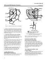
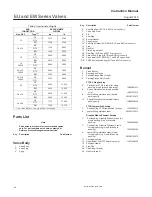
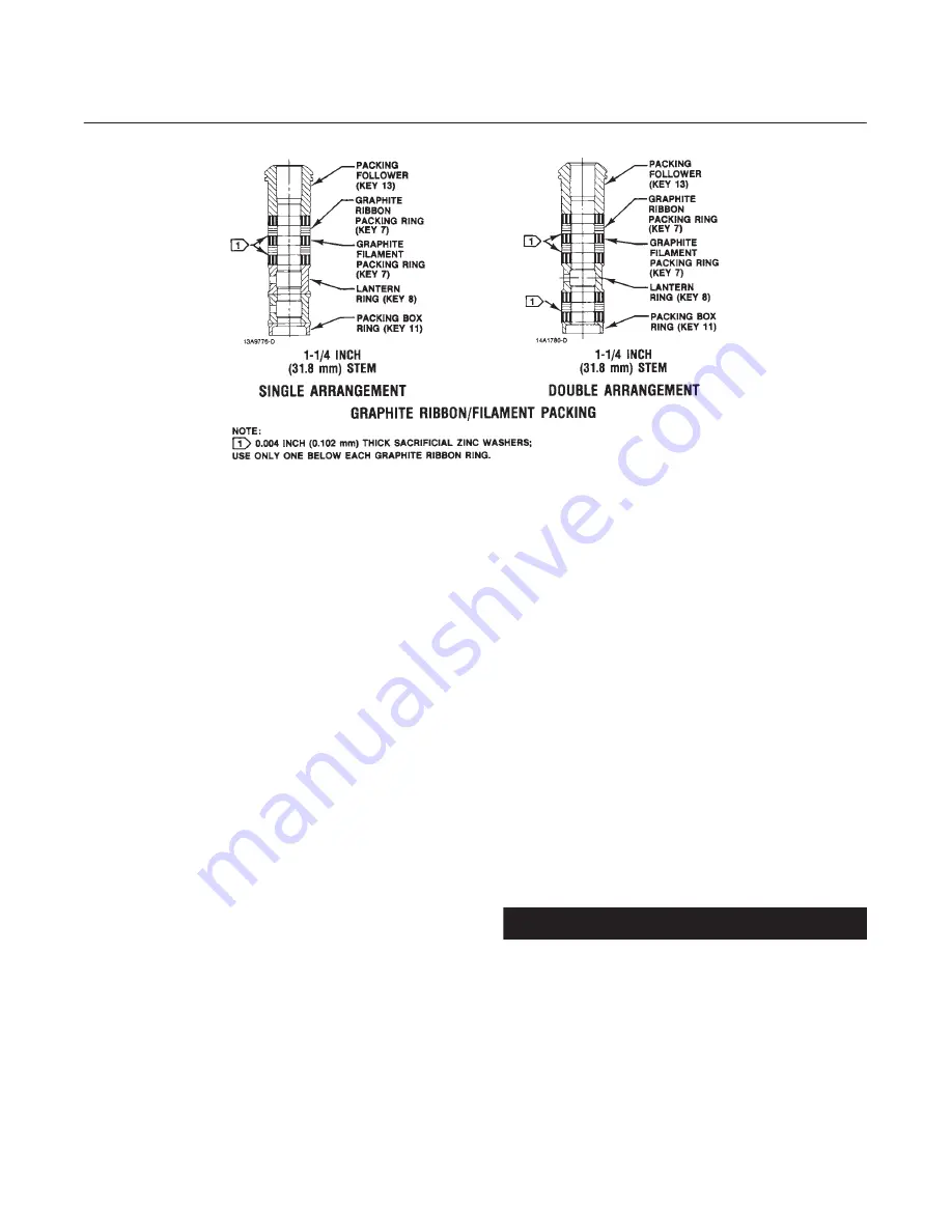
Figure 4. Typical Packing (Continued)
A6060/IL
Packing Maintenance
This procedure does not cover ENVIRO-SEAL or
HIGH-SEAL packing; refer to separate manuals for
instructions on those packing types.
Key numbers are shown in figure 4 unless otherwise
indicated.
For spring-loaded single PTFE V-ring packing, the
spring (key 8) maintains a sealing force on the
packing. If leakage is noted around the packing
follower (key 13), check to be sure the shoulder on
the packing follower is touching the bonnet. If the
shoulder is not touching the bonnet, tighten the
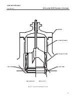
packing flange nuts (key 5, figure 5) until the
shoulder is against the bonnet. If leakage cannot be
stopped in this manner, proceed to the Replacing
Packing section.
If there is undesirable packing leakage with other
than spring-loaded packing, first try to limit the
leakage and establish a stem seal by tightening the
packing flange nuts.
If the packing is relatively new and tight on the stem
and if tightening the packing flange nuts does not
stop the leakage, it is possible that the valve stem is
worn or nicked so that a seal cannot be made. The
surface finish of a new valve stem is critical for
making a good packing seal. If the leakage comes
from the outside diameter of the packing, it is
possible that the leakage is caused by nicks or
scratches around the packing box wall. If performing
any of the following procedures, inspect the valve
stem and packing box wall for nicks and scratches.
Replacing Packing
1. Isolate the control valve from the line pressure,
release pressure from both sides of the valve body,
and drain the process media from both sides of the
valve. If using a power actuator, also shut off all
pressure lines to the power actuator, release all
pressure from the actuator, and use lock-out
procedures to prevent injury while you work on the
equipment.
2. Remove any leak-off piping from the bonnet.
Disconnect the stem connector, and then remove
the actuator from the valve by unscrewing the hex
nuts (key 26, figure 5).
3. Loosen the packing flange nuts (key 5, figure 5)
so that the packing is not tight on the valve stem.
Remove any travel indicator parts and stem locknuts
from the valve stem threads.
CAUTION
Avoid damage to the seating surfaces
caused by the valve plug and stem
assembly dropping from the bonnet
after being lifted part way out.
When lifting the bonnet (key 1, figure
5), either be sure that the valve plug
and stem assembly remains in the
valve and on the seat or, temporarily
install a valve stem locknut on the


