background image


Service Manual 

Air-to-Water Heat pump 


WARNING 


This service information is designed for experienced repair technicians only and is not designed for use by the general public. 


It does not contain warnings or cautions to advise non-technical individuals of potential dangers in attempting to service a product. 


Products powered by electricity should be serviced or repaired only by experienced professional technicians. Any attempt to service or 

repair the products dealt with in this service information by anyone else could result in serious injury or death. 

PRECAUTION OF LOW TEMPERATURE 

In order to avoid frosting, be assured of no refrigerant leakage during the installation or repairing of refrigerant circuit. 

Summary of Contents for FHIF-WHS-120CE3

Page 1: ...otential dangers in attempting to service a product Products powered by electricity should be serviced or repaired only by experienced professional technicians Any attempt to service or repair the pro...

Page 2: ......

Page 3: ...Features 13 3 1 Outdoor unit 13 3 2 Hydronic module 14 4 Operation range 15 5 Sound pressure level 16 6 Accessories 18 7 Performance data 19 7 1 Heating capacity 19 8 System diagram 21 9 Wiring diagra...

Page 4: ...and control 58 13 1 Icon introduction 58 13 2 Setting the clock 59 13 3 Running mode and temperature setting 60 13 4 Display shows 61 13 5 Electric auxiliary heating 62 13 6 Forced defrosting 62 13 7...

Page 5: ...on cord for power supply cord Do not share the single outlet with other electrical appliances Poor contact poor insulation or over current will cause electrical shock or fire 2 Do not tie up the power...

Page 6: ...19 This equipment is strongly recommended to be installed with Residual Current Device RCD on site according to the respective national wiring rules or country specific safety measures in terms of res...

Page 7: ...contact hot part i e refrigerant piping to prevent from insulation failure melt 5 Do not apply excessive force to water pipes that may damage the pipes If water leakage occurs it will cause flooding a...

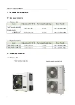
Page 8: ...3 61 220 240V 1Ph 50Hz 1014 1430 450 124 138 380 415V 3Ph 50Hz 1 1 2 Hydronic module Model Dimension W H D Net Gross Weight kg Power Supply 490 910 340 48 56 220 240V 1Ph 50Hz 490 910 340 48 56 220 2...

Page 9: ...R32 ATW Service Manual 7 1 2 2 Hydronic module FHIF WHS 120CE3 FHIF WHS 160CE3...

Page 10: ...general water outlet W 35 water outlet W 55 SCOP 5 15 3 35 Sound pressure level dB A 60 Physical data Dimension W H D mm 1032x810x445 Packing W H D mm 1075 875 495 Net gross weight kg 56 3 61 Compress...

Page 11: ...5 88 Max piping length m 20 Max height difference Outdoor unit upside m 10 Outdoor unit downside m 10 Refrigerant Type R32 Quantity kg 3 Throttle type EXV Additional charge g Total pipe length 5 m 30g...

Page 12: ...0 Packing W H D mm 1095 1545 485 Net gross weight kg 124 138 Compressor Brand GMCC Type Rotary DC Inverter Model EKTQ420D1UMU Poles 6 Speed rps 12 120 Oil POE 1400mL Outdoor fan Brand Yongan Motor typ...

Page 13: ...88 Max piping length m 50 Max height difference Outdoor unit upside m 20 Outdoor unit downside m 20 Refrigerant Type R32 Quantity kg 3 8 Throttle type EXV Additional charge g Total pipe length 5 m 30...

Page 14: ...g connectio n Dia Outlet mm DN32 DN32 Inlet mm DN32 DN32 Safty valve kPa 600 600 Drainage pipe Dia mm DN20 DN20 Expansion tank Volume L 2 2 Max water pressure kPa 800 800 Pre pressure kPa 150 150 Wate...

Page 15: ...ing up to 30 meter with height difference 20 meter no need extra refrigerant within 5m refrigerant pipe length Heating cooling domestic hot water mode total heat solution Pic 3 1 Total heat solution W...

Page 16: ...e heating energy efficiency is up to A 35 and 55 3 2 Hydronic module All hydronic components are pre assembled easy for installation Backup E heater for additional heating during extremely cold outdoo...

Page 17: ...R32 ATW Service Manual 15 4 Operation range Pic 4 1 Heating mode operation range Pic 4 2 Cooling mode operation range...

Page 18: ...R32 ATW Service Manual 16 Pic 4 3 Domestic hot water mode operation range...

Page 19: ...ide Microphone 1 m body height 1 2 m Microphone Pic 5 1 Outdoor unit sound test diagram Model Sound pressure level dB A 57 59 Hydronic module Pic 5 2 Hydronic module sound test diagram Model Sound pre...

Page 20: ...ion wire 1 25m 5 core communication wire Y type filter 1 Connected in water inlet pipe Wall mounted board 1 Temperature sensor 1 5k for DHW tank Cable ties 3 Wired controller cover 1 Outdoor unit inst...

Page 21: ...9 60 3 50 2 74 6 80 2 83 2 40 15 12 11 50 2 35 4 89 11 30 2 37 4 76 10 78 2 41 4 48 10 48 2 78 3 77 9 98 3 16 3 16 9 80 3 46 2 83 7 00 3 38 2 07 20 15 11 70 1 74 6 74 11 60 1 97 5 88 10 98 2 08 5 29 1...

Page 22: ...8 4 77 2 28 15 12 18 40 3 96 4 64 18 08 4 00 4 52 17 60 4 06 4 33 17 28 4 69 3 68 16 80 5 32 3 16 15 68 5 84 2 68 11 20 5 71 1 96 20 15 18 72 2 93 6 40 18 56 3 33 5 58 17 92 3 50 5 12 17 60 4 10 4 29...

Page 23: ...R32 ATW Service Manual 21 8 System diagram...

Page 24: ...R32 ATW Service Manual 22 9 Wiring diagram 9 1 Outdoor unit 9 1 1 9 1 2 FHOF WHS 100CE3 FHOF WHS 160CE3 3F...

Page 25: ...ure sensor CN37 DOWN DC FAN 5 UP DC FAN 5 5 15V 4 WAY SV1 SV2 4 WAY SV2 CN36 N N N N HEATER TRANS1 INDOOR COMM SW3 12 min 3 min Factory Default 0 15 16 31 SW4 32 47 48 63 0 15 0 15 0 15 0 15 address 1...

Page 26: ...R32 ATW Service Manual 24 9 2 Hydronic module L1 N1 2 3 1 4 E Q P L1 H C P_o N IC 5 6 7 4 3 1 2 3 2 1 5 4 3 1 2 4 3 2 1 1 2 1 2 M L N 3 2 1 Reserved 16...

Page 27: ...R32 ATW Service Manual 25 9 3 Printed circuit board 1 Single phase outdoor unit Main integrated PCB Display board 2 3 phase outdoor unit...

Page 28: ...R32 ATW Service Manual 26 Main PCB 3 Hydronic module Main PCB...

Page 29: ...R32 ATW Service Manual 27 Filter board...

Page 30: ...nt panel 4 2 Fan blade 15 Small handler 5 Left side plate 16 Seat plate 6 Top cover plate assy 17 Inverter compressor 7 EC part 18 Gas liquid separator 7 1 Integrated main PCB 19 Gas return pipe 7 2 D...

Page 31: ...4 4 Filter board 6 Middle partition part 14 5 IPM board 7 Maintenance panel 15 Top cover panel with cotton 8 Right side panel 16 Chassis 9 Big handler with cotton 17 Gas liquid separator 10 Seat plate...

Page 32: ...in PCB 7 Foam 2 21 3 Filter board 8 Front panel 21 4 Relay 9 Pressure gauge 21 5 Thermostat 10 Wired controller 21 6 Thermostat 11 Wired controller panel 22 Plate heat exchanger support 12 Water pump...

Page 33: ...lectrical connection Avoid installations in areas where the ambient temperature may drop below 28 C for outdoor unit If an awning is built over the unit to prevent direct sunlight or rain be careful t...

Page 34: ...R32 ATW Service Manual 32 Model FHOF WHS 160CE3 3F...

Page 35: ...R32 ATW Service Manual 33 Single unit installation More than one unit installation Unit mm...

Page 36: ...l wall When install electrical equipment at wooden building of metal lath or wire lath according to electrical facility technical standard no electrical contact between equipment and building is allow...

Page 37: ...ort that is fully reliable and safe to withstand twice the weight of the unit The mounting wall panel is strong and solid enough to prevent it from vibration Always mount the installation plate horizo...

Page 38: ...will not be easily discharged causing the unit malfunction 11 2 4 Wired controller The hydronic module is standard with a touch screen wired controller The wired controller can be taken away from hyd...

Page 39: ...d torque as stated in the table 1 Cutting and flaring Please cut using pipe cutter and then remove the burrs Remove the burrs by using reamer If burrs is not removed gas leakage may be caused Turn the...

Page 40: ...he required accessory pipe can be long or short to avoid affecting the capacity from too long cooling pipe please select a reasonable tube length according to table below try to select the location of...

Page 41: ...e the pipe When the refrigerant piping is installed foreign matter inside the pipe must be removed with high pressure nitrogen The hydronic module shall not be connected during cleaning It is not poss...

Page 42: ...id pipe diameter mm Pipe length m Adding amount of refrigerant kg 9 52 5 9 52 5 Add 0 03kg for each additional 1m Note R32 refrigerant must be charged in liquid form with fixed amount measured by elec...

Page 43: ...orm the piping to excessive force when doing piping connection job Use DN32 nut for both water inlet and outlet connection and clean all pipes with tap water before connecting to the indoor unit Cover...

Page 44: ...rew the exhaust valve on the hydronic module and fill the water system of the hydronic module The air in the system can be gradually discharged through the exhaust valve and the water outlet of the wa...

Page 45: ...Open the water tank outlet and drain valve 4 Follow the steps below to drain the water from the hydronic module a Turn off the power b Close the water supply valve c Open the drain valves on the circ...

Page 46: ...R32 ATW Service Manual 44 HEATING MODE COOLING MODE...

Page 47: ...R32 ATW Service Manual 45 HEATING MODE WITHOUT COOLING MODE DHW MODE WITHOUT COOLING MODE...

Page 48: ...R32 ATW Service Manual 46 HEATING MODE WITHOUT DHW MODE AND DHW TANK ONLY DHW MODE...

Page 49: ...onal electric standard Power wiring should be engaged by specialized electrician The field wiring must be carried out in accordance with the wiring diagram supplied with the unit The power cable and s...

Page 50: ...lded cable as the signal cable connect the shielded mesh to E of the terminal block When using the 3 core shielded cable as the signal cable the shielded mesh must be grounded It is absolutely forbidd...

Page 51: ...ooster heater filed supply J Electric 3 way valve filed supply K Circulation water pump filed supply L Electric 2 way valve filed supply M FCU N Room thermostat filed supply O Radiator filed supply P...

Page 52: ...le Equipment must be grounded All high voltage external loads if it is metal or a grounded port must be grounded All external loads current are needed less than 3A if the loads current is greater than...

Page 53: ...Please use a normal closing valve for this unit 3 Connection of 3 way valve When the unis is in DHW mode SV4 has 220V output When the unit is in cooling mode or heating mode SV4 has no output Wiring o...

Page 54: ...ng temperature is 7 If both signals are connected or disconnected the unit is OFF 5 Connection of REMO_CTRL The REMO_CTRL is used to remotely start and stop the units It is short circuited at the fact...

Page 55: ...booster heater An additional contactor is needed and a dedicated terminal is needed to supply power to the booster heater 7 Connection of circulation water pump Connection of the circulation depends o...

Page 56: ...R32 ATW Service Manual 54 When the unit has error code alarm port has a 220V output...

Page 57: ...hase outdoor unit Capacity setting S1 0 1 2 3 4 Reserved 2 3 phase outdoor unit Start time setting SW3 Start time 12 min Start time 3 min Factory default Capacity setting SW6 3 Hydronic module factory...

Page 58: ...er tank installed Ground wiring Make sure that the ground wires have been connected properly and that the ground terminals are tightened Internal wiring Visually check the EC box for loose connections...

Page 59: ...R32 ATW Service Manual 57...

Page 60: ...rd controlling the operating status of the system through touch keys and displaying the working status of the whole system through its LCD screen 13 1 Icon introduction Anti freezing Error Cooling mod...

Page 61: ...ress this button to confirm the settings exit all interfaces of setting or query and return to the main interface 13 2 Setting the clock 1 Short press setting button the clock icon flashes 2 Long pres...

Page 62: ...ain interface and when the unit is ON short press or to enter heating cooling water temperature TS1 setting interface left digital tube flashes b Press or button to choose the target temperature Press...

Page 63: ...the target temperature Press button once to increase the setting temperature by 1 C When the setting temperature reaches the highest or lowest value press the button again that the setting temperatur...

Page 64: ...d If the unit is in heating mode or DHW mode and T3 outdoor unit heat exchanger temperature is lower than 15 the unit will enter forced defrosting mode 13 7 Sterilization mode Long press mode setting...

Page 65: ...ton again to cancel the selection the icon flashes and you can reset it 5 Mode setting After finishing minutes setting long press to enter the timer mode setting Short press to choose mode The operati...

Page 66: ...l clear weekly settings 13 9 Power down memory setting In main interface press setting button three times and middle digital tube displays 1 meaning the controller with power down memory default Press...

Page 67: ...unction E1 Communication failure between hydronic module and outdoor unit E9 Communication failure between hydronic module and wired controller E2 Water outlet temperature sensor T1 malfunction EF Mod...

Page 68: ...or unit 50 80 100 120 140 160 2 Total capacity of indoor units 3 Total required capacity after correction of outdoor unit 4 Operation mode 0 Standby 2 Cooling 3 Heating 4 Forced cooling 5 Actual opera...

Page 69: ...t check No Display content Remarks 1 Capacity of outdoor unit 2 Set mode of indoor unit 3 Operating mode of outdoor unit 0 Standby 2 Cooling 3 Heating 4 Forced cooling 4 Operating capacity demand for...

Page 70: ...perature T7 When hydronic module is without DHW function it will show 0 9 Capacity of hydronic module Capacity HP value 0 1 10 Operating capacity demand of hydronic module Capacity HP value 0 1 11 Wat...

Page 71: ...r 3 times within 30 minutes It can only be restored by repowering on the unit The same with P6 H5 Display P2 protection f or 3 times within 30 minutes It can only be restored by repowering on the unit...

Page 72: ...ctly And install the EXV coil in the right location P3 Primary current overcurrent protection P4 Exhaust temperature is too high protection 3 times P4 protection appears within 100 minutes and then re...

Page 73: ...times P9 protection appears within 10 minutes and then reported H9 L0 DC compressor module failure L1 DC bus low voltage protection L2 DC bus high voltage protection L4 MCE fault synchronization clos...

Page 74: ...or E8 Tw_out fault of heat exchanger outlet water temperature 1 The sensor connector is loosening Reconnect it 2 The sensor connector is wet or there is water in Remove the water make the connector dr...

Page 75: ...is on the highest speed 7 Make sure that the expansion tank is not broken 8 Check that the resistance in the water circuit is not too high for the pump P2 Protection for insufficient water flow P3 T1...

Reviews: