R32 ATW Service Manual
69
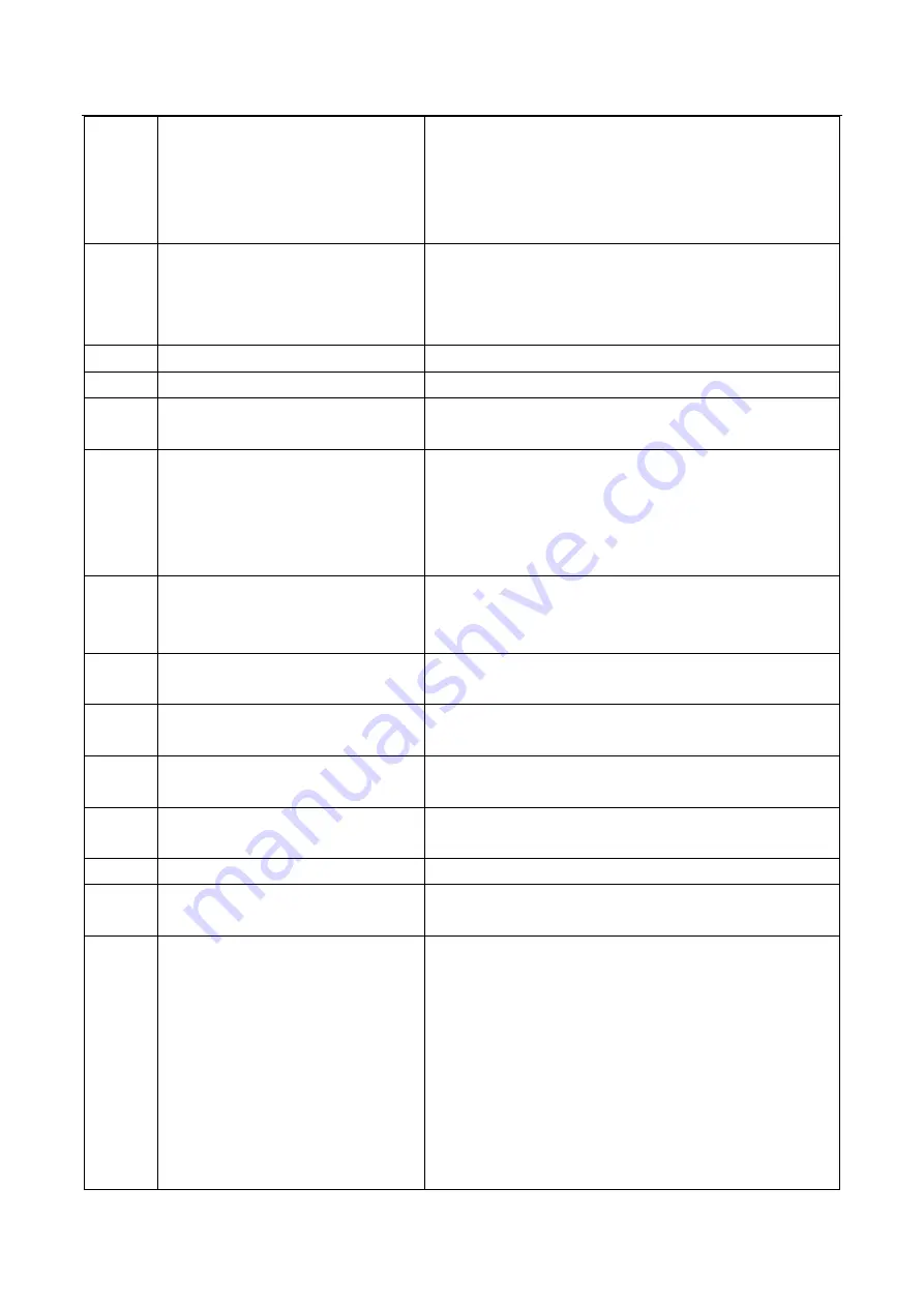
2. Communication wire sequence is not right. Reconnect the
wire in the right sequence.
3. Whether there is a high magnetic field or high power
interfere, such as lifts, large power transformers, etc. To add a
barrier to protect the unit or to move the unit to the other place.
E4
Ambient temperature sensor failure
1. The T4 sensor connector is loosening. Reconnect it.
2. The T4 sensor connector is wet or there is water in. Remove
the water, make the connector dry. Add waterproof adhesive
3. The T4 sensor failure, change a new sensor.
E6
Condenser temperature sensor failure The same with E4.
E8
T5 exhaust temperature sensor failure The same with E4.
E9
AC over voltage/ under voltage
protection
E10
EEPROM failure
1. The EEPROM parameter is error, rewrite the EEPROM
data.
2. EEPROM chip part is broken. Change a new EEPROM
chip part.
3. Main PCB is broken, change a new PCB.
H0
Communication failure between the
main control chip and the module
board
H4
Display P6 protection f or 3 times
within 30 minutes
It can only be restored by repowering on the unit.
The same with P6.
H5
Display P2 protection f or 3 times
within 30 minutes
It can only be restored by repowering on the unit.
The same with P2.
H6
Display P4 protection f or 3 times
within 100 minutes
It can only be restored by repowering on the unit.
The same with P4.
H9
Display P9 protection f or 2 times
within 10 minutes
It can only be restored by repowering on the unit.
The same with P9.
H8
High pressure sensor failure
Cause: Exhaust pressure Pc<0.3MPa
H10
Display P3 protection f or 3 times
within 60 minutes
It can only be restored by repowering on the unit.
The same with P3 and P14.
P1
High pressure protection (high
voltage switch)
Heating mode, DHW mode:
1. The water flow is low; water temp is high, whether there
is air in the water system. Release the air.
2. Water pressure is lower than 0.1Mpa, charge the water to
let the pressure in the range of 0.15~0.2Mpa.
3. Over charge the refrigerant volume. Recharge the
refrigerant in right volume.
4. EXV locked or coil connector is loosening. Tap-tap the
valve body and plug in/ plug off the connector for several
times to make sure the valve is working correctly. And
Summary of Contents for FHIF-WHS-120CE3
Page 2: ......
Page 9: ...R32 ATW Service Manual 7 1 2 2 Hydronic module FHIF WHS 120CE3 FHIF WHS 160CE3...
Page 18: ...R32 ATW Service Manual 16 Pic 4 3 Domestic hot water mode operation range...
Page 23: ...R32 ATW Service Manual 21 8 System diagram...
Page 28: ...R32 ATW Service Manual 26 Main PCB 3 Hydronic module Main PCB...
Page 29: ...R32 ATW Service Manual 27 Filter board...
Page 34: ...R32 ATW Service Manual 32 Model FHOF WHS 160CE3 3F...
Page 35: ...R32 ATW Service Manual 33 Single unit installation More than one unit installation Unit mm...
Page 46: ...R32 ATW Service Manual 44 HEATING MODE COOLING MODE...
Page 47: ...R32 ATW Service Manual 45 HEATING MODE WITHOUT COOLING MODE DHW MODE WITHOUT COOLING MODE...
Page 48: ...R32 ATW Service Manual 46 HEATING MODE WITHOUT DHW MODE AND DHW TANK ONLY DHW MODE...
Page 56: ...R32 ATW Service Manual 54 When the unit has error code alarm port has a 220V output...
Page 59: ...R32 ATW Service Manual 57...


