11
4. Diagrams
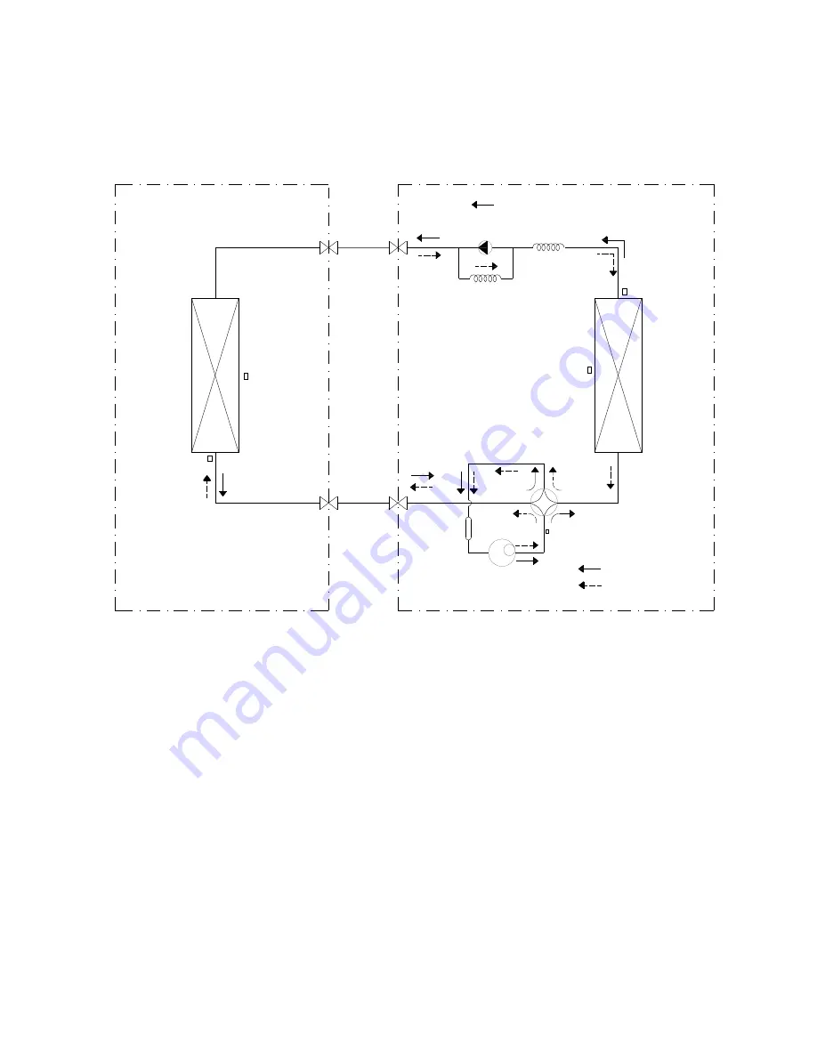
4.1 Refrigerant Cycle Diagram
CHECK VALVE
(Heating Model only)
CAPILIARY TUBE
LIQUID SIDE
GAS SIDE
HEAT
EXCHANGE
(EVAPORATOR)
HEAT
EXCHANGE
(CONDENSER)
Compressor
2-WAY VALVE
3-WAY VALVE
4-WAY VALVE
COOLING
HEATING
T2 Evaporator
temp. sensor
T1 Room temp.
sensor
T3 Condenser
temp. sensor
Accumulator
T5 Discharge temp. sensor
T4 Ambient
temp. sensor
INDOOR
OUTDOOR
Summary of Contents for FSAI-SU-120AE2
Page 12: ...12 4 2 Wiring Diagram Indoor unit FSAI SU 90AE2 FSAI SU 120AE2 Outdoor unit FSOAI SU 90AE2 ...
Page 13: ...13 Outdoor unit FSOAI SU 120AE2 ...
Page 45: ...45 8 2 6 Refrigerant Leakage Detection diagnosis and solution EC ...
Page 46: ...46 8 2 7 IPM malfunction or IGBT over strong current protection diagnosis and solution P0 ...
Page 47: ...47 8 2 8 Over voltage or too low voltage protection diagnosis and solution P1 ...
Page 48: ...48 8 2 9 High temperature protection of compressor top diagnosis and solution P2 ...
Page 49: ...49 8 2 10 Inverter compressor drive error diagnosis and solution P4 ...


