background image

www.Fisher.com

Fisher

 LCP200 Local Control Panel

Contents

Introduction

1

. . . . . . . . . . . . . . . . . . . . . . . . . . . . . . . . .

Scope of Manual

1

. . . . . . . . . . . . . . . . . . . . . . . . . . . . .

Description

2

. . . . . . . . . . . . . . . . . . . . . . . . . . . . . . . . .

Specifications

2

. . . . . . . . . . . . . . . . . . . . . . . . . . . . . . .

Educational Services

2

. . . . . . . . . . . . . . . . . . . . . . . . . . .

Installation

6

. . . . . . . . . . . . . . . . . . . . . . . . . . . . . . . . . .

Hazardous Area Classifications and Special

Instructions for “Safe Use” and Installation
in Hazardous Areas

6

. . . . . . . . . . . . . . . . . . . . . . . .

Mounting

6

. . . . . . . . . . . . . . . . . . . . . . . . . . . . . . . . . .

Electrical Connections

7

. . . . . . . . . . . . . . . . . . . . . . . .

Setup

14

. . . . . . . . . . . . . . . . . . . . . . . . . . . . . . . . . . . . . .

Principle of Operation

15

. . . . . . . . . . . . . . . . . . . . . . . .

Operation Verification

16

. . . . . . . . . . . . . . . . . . . . . . . .

Maintenance

17

. . . . . . . . . . . . . . . . . . . . . . . . . . . . . . . .

Replacing the LED Assembly

17

. . . . . . . . . . . . . . . . . .

Replacing the LED Assembly with an 

LED Light Cover

18

. . . . . . . . . . . . . . . . . . . . . . . . . .

Replacing the Front Panel Assembly

18

. . . . . . . . . . .

Troubleshooting

19

. . . . . . . . . . . . . . . . . . . . . . . . . . . .

Parts Ordering

20

. . . . . . . . . . . . . . . . . . . . . . . . . . . . . . .

Parts Kits

20

. . . . . . . . . . . . . . . . . . . . . . . . . . . . . . . . . . .

Figure 1. Fisher LCP200 Local Control Panel

X1536

Introduction

Scope of Manual

This instruction manual includes installation and maintenance information for the Fisher LCP200 local control panel
(figure 1). This device is used with Fisher FIELDVUE™ instruments in Safety Instrumented Systems (SIS). Refer to
instruction manual DVC6200 SIS Digital Valve Controllers for Safety Instrumented System (SIS) Solutions,

D103557X012

 or DVC6000 SIS Digital Valve Controllers for Safety Instrumented System (SIS) Solutions,

D103230X012

 for additional information.

Unless otherwise noted, the information in this instruction manual applies to both DVC6200 SIS and DVC6000 SIS
digital valve controllers. For simplicity, the DVC6200 SIS model name will be used throughout.

Instruction Manual

D104296X012

LCP200 Local Control Panel

August 2018

Summary of Contents for LCP200

Page 1: ... Control Panel X1536 Introduction Scope of Manual This instruction manual includes installation and maintenance information for the Fisher LCP200 local control panel figure 1 This device is used with Fisher FIELDVUE instruments in Safety Instrumented Systems SIS Refer to instruction manual DVC6200 SIS Digital Valve Controllers for Safety Instrumented System SIS Solutions D103557X012 or DVC6000 SIS...

Page 2: ... panel is used with the HARTr communicating DVC6200 SIS digital valve controller This panel is used to manually open and close a safety shutdown valve The LCP200 can be configured to auto or manual reset after a trip It also offers a smart auto reset configuration which requires a manual reset for locally initiated trips but auto reset for all other trips Additionally it includes a button for init...

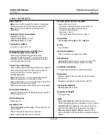
Page 3: ... Category II per IEC 61010 clause 5 4 2d Electrical Housing IP66 Type 4X Hazardous Area FM United States and Canada Intrinsically Safe for Gas and Dust ATEX Intrinsically Safe for Gas and Dust IECEx Intrinsically Safe for Gas and Dust Electromagnetic Interference EMI Meets EN 61326 1 2013 Immunity Industrial locations per Table 2 of EN 61326 1 Standard Performance is shown in table 2 below Emissio...

Page 4: ...uired for Auto detection of power source 4 DVC6200 SIS FW7 or later is required for the test contact to change state Table 2 Electromagnetic Immunity Performance for Fisher LCP200 Port Phenomenon Basic Standard Test Level Performance Criteria 1 Enclosure Electrostatic discharge ESD IEC 61000 4 2 4 kV contact 8 kV air A Radiated EM field IEC 61000 4 3 80 to 1000 MHz 10V m with 1 kHz AM at 80 1400 t...

Page 5: ...Instruction Manual D104296X012 LCP200 Local Control Panel August 2018 5 Figure 2 Fisher LCP200 Local Control Panel Dimensions 94 3 7 288 11 3 406 16 143 5 6 165 6 5 105 4 1 mm INCH NOMINAL 8 5 mm ...

Page 6: ...ol Panel D104369X012 D ATEX Hazardous Area Approvals LCP200 Local Control Panel D104370X012 D IECEx Hazardous Area Approvals LCP200 Local Control Panel D104371X012 All documents are available from your Emerson sales office or Fisher com Contact your Emerson sales office for all other approval certification information Mounting Refer to figure 2 for dimensional information The LCP200 local control ...

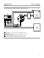
Page 7: ...llow the local regional and national codes could result in personal injury or property damage from fire or explosion Refer to the appropriate wiring diagram as defined in table 3 based on your installation requirements Also refer to figure 5 for LCP200 terminal connections label details and information as well as DVC6200 SIS terminal box details When connecting the wiring terminals tighten to a to...

Page 8: ... requirements must be met Uo Ui Io Ii Po Pi Co Ci Cc Lo Li Lc When installing the terminal cover use a 4 mm hex key to tighten the screws evenly in a criss cross pattern such as the one indicated in figure 4 to a torque of 8 7 N m 77 lbf in 10 to help ensure the cover is properly installed Apply silicone lubricant to the terminal box O ring key 7 figure 10 Figure 4 Proper Cover Installation NOTE T...

Page 9: ...00 and FIELDVUE DVC6200 SIS LCP200 INTERIOR DVC6200 SIS TERMINAL BOX INTERIOR TALK TALK LOOP LOOP AUX AUX EARTH GROUND SAFETY GROUND GG54648 Sheet 5 AUX AUX LOOP LOOP SAFETY GROUND RESET TEST TRIP 24VDC 24VDC ELECTRICAL ENTRY 3 4 NPT OR M20 24V POWER AUX LOOP DVC6200 SIS RESET TEST TRIP NOT AVAILABLE EARTH GROUND ...

Page 10: ...G TO 1 RESET CONTACT 2 CONNECT EITHER NO C OR NC C TERMINALS OF RESET TRIP AND TEST CONTACTS SHOWN 1 ABOVE IS RESET NO C TERMINALS 3 USE METAL CONDUIT FOR CABLING BETWEEN DVC6200 SIS AND LCP200 AS EMI SHIELD 4 THE DIGITAL INPUT DOES NOT NEED TO BE CONNECTED FOR THE LCP200 TO OPERATE LCP200 GG22618 SHEET 2 3 1 DVC6200 SIS TERMINAL BOX 8 20 mA DIGITAL IN ANALOG OUT 2 24V POWER AUX LOOP DVC6200 SIS T...

Page 11: ...CABLING TO 1 RESET CONTACT 2 CONNECT EITHER NO C OR NC C TERMINALS OF RESET TRIP AND TEST CONTACTS SHOWN 1 ABOVE IS RESET NO C TERMINALS 3 USE METAL CONDUIT FOR CABLING BETWEEN DVC6200 SIS AND LCP200 AS EMI SHIELD 4 THE DIGITAL INPUT DOES NOT NEED TO BE CONNECTED FOR THE LCP200 TO OPERATE LCP200 3 1 DVC6200 SIS TERMINAL BOX DIGITAL IN 24 VDC SOURCE 2 USER SUPPLIED OUTPUT 4 20 mA TALK AUX LOOP OUT ...

Page 12: ...NECT EITHER NO C OR NC C TERMINALS OF RESET TRIP AND TEST CONTACTS SHOWN 1 ABOVE IS RESET NO C TERMINALS 3 USE METAL CONDUIT FOR CABLING BETWEEN DVC6200 SIS AND LCP200 AS EMI SHIELD 4 THE DIGITAL INPUT DOES NOT NEED TO BE CONNECTED FOR THE LCP200 TO OPERATE LOGIC SOLVER USER SUPPLIED LCP200 1 DVC6200 SIS TERMINAL BOX DIGITAL IN OUTPUT 24 VDC 2 LC340 LINE CONDITIONER TALK AUX LOOP OUT CAL AUX LOOP ...

Page 13: ...EITHER NO C OR NC C TERMINALS OF RESET TRIP AND TEST CONTACTS SHOWN 1 ABOVE IS RESET NO C TERMINALS 3 USE METAL CONDUIT FOR CABLING BETWEEN DVC6200 SIS AND LCP200 AS EMI SHIELD 4 THE DIGITAL INPUT DOES NOT NEED TO BE CONNECTED FOR THE LCP200 TO OPERATE LOGIC SOLVER USER SUPPLIED 3 1 DVC6200 SIS TERMINAL BOX DIGITAL IN 24 VDC SOURCE 2 LC340 LINE CONDITIONER OPUTPUT 24 VDC USER SUPPLIED TALK CAL AUX...

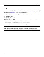
Page 14: ... Enter Supply Pressure and Unit Enter Actuator Make Model and Size Enter Partial Stroke test Starting Point Relay Type and Zero Power Condition select the instrument connected to local control panel LCP200 option D Use Device Setup to configure the digital valve controller with the LCP200 D Continue to set up the digital valve controller according the normal set up procedure D Remember to place th...

Page 15: ...tuck in the tripped state Fast Blink 1 2 second The valve is at mid travel after a trip The valve may be moving or stuck in this position Bottom Yellow Ready to Reset Solid The valve may be reset to the normal operating state Reset to Normal State Notes 1 If the top middle and bottom lights are blinking in sequence then the DVC6200 SIS is out of service In point to point mode the DVC6200 SIS will ...

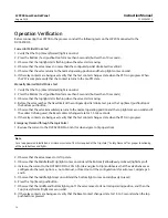
Page 16: ...shbutton 5 Observe that the valve immediately returns to the normal operating position and the top light comes on solid and if the contact is being used the Reset contact changes state for 1 5 to 3 seconds 6 If the relay contacts are being used verify that the Test contact changes state when the PST is in progress Emergency Demand through the Logic Solver 1 Reduce the current to the DVC6200 SIS to...

Page 17: ...ich includes the relay contacts can be replaced as an assembly The LCP200 enters a bench mode when it is powered and not connected to a digital valve controller i e the auxiliary terminals are not connected to the DVC6200 SIS In this mode the light next to each button will be on solid when the button is pressed The corresponding relay contact will change state as long as the respective button is p...

Page 18: ...l Assembly WARNING Disconnect power and remove the LCP200 from service before replacing the front panel assembly Person injury or property damage may result if power is not disconnected CAUTION Ensure the front panel assembly is not exposed to dust moisture or other contaminants during this procedure Exposure to dust moisture or other contaminants can damage the electronics 1 Disconnect the LCP200...

Page 19: ...n requires 8 mA current to operate Ensure that there is sufficient current 4 The LCP200 and the digital valve controller are properly connected and there is sufficient current but the lights are not lit 4 The LED may be damaged 4 Replace LED If possible take the LCP200 to bench mode and verify that the LED does not light up when the corresponding button is pressed 5 Lights are blinking 5 Valve is ...

Page 20: ...2 key 45 LED light cover qty 3 key 33 3 Soft Parts Kit see figure 10 GG54647X012 Includes LED base O ring qty 8 key 46 Terminal O ring qty 1 key 7 Panel O ring qty 1 key 44 Kit Description Part Number 4 Front Panel Assembly Kits see figure 11 Note The Front Panel Assembly Kits contain LEDs and included buttons pre assembled on the front panel assembly key 30 It also includes the panel O ring key 4...

Page 21: ...ction Manual D104296X012 LCP200 Local Control Panel August 2018 21 Figure 10 Fisher LCP200 Assembly GG54648 2 14 4 12 16 APPLY LUBRICANT SEALANT TORQUE SEAL 34 GREEN 35 RED 36 YELLOW 32 46 38 39 7 28 44 28 28 ...

Page 22: ...l D104296X012 LCP200 Local Control Panel August 2018 22 GREEN 34 RED 35 YELLOW 36 Figure 11 Front Panel Assembly GG54648 30 32 45 46 47 44 33 14 12 304 305 40 39 38 16 28 28 28 16 16 APPLY LUBRICANT SEALANT TORQUE SEAL ...
Page 23: ...Instruction Manual D104296X012 LCP200 Local Control Panel August 2018 23 ...
Page 24: ... request We reserve the right to modify or improve the designs or specifications of such products at any time without notice E 2018 Fisher Controls International LLC All rights reserved Fisher and FIELDVUE are marks owned by one of the companies in the Emerson Automation Solutions business unit of Emerson Electric Co Emerson Automation Solutions Emerson and the Emerson logo are trademarks and serv...

Reviews: