background image

Lit. No. 43069, Rev. 05 

May 1, 2019

86000, 86000-1, 86100(CH), 86100-1(CH), 86200, 86205, 86205-1, 86300, 86400 

86600-3, 86610-3(CH), 87000, 87000-1, 87100, 87200, 87300, 87400, 87600-3

1/4-20

109

154

1/4-28

121

171

5/16-18

150

212

5/16-24

170

240

3/8-16

269

376

3/8-24

297

420

7/16-14

429

606

7/16-20

9/16-12
9/16-18

5/8-11
5/8-18
3/4-10
3/4-16

7/8-9

7/8-14

474

669

644

909

1-8

1-12

704

995

1/2-13

1/2-20

11.9
13.7

24.6

27.3

43.6

26.9
53.3

93

148

49.4
69.8

77.9

106.4
120.0

8.4
9.7

17.4

19.2
30.8
35.0
49.4
55.2
75.3
85.0

M6 x 1.00

M12 x 1.75

M8 x 1.25

M14 x 2.00

M10 x 1.50

M27 x 3.00

M22 x 2.50

M30 x 3.50

M24  x 3.00

M20 x 2.50

11.1

19.5
38.5

67

107

7.7

613

778

1139

1545

450

428
562
796

1117

M33 x 3.50
M36 x 4.00

2101
2701

1468
1952

325

M16 x 2.00

231

167

M18 x 2.50

318

222

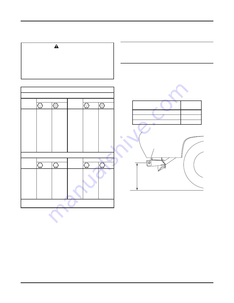
Recommended Fastener Torque Chart

Size

Size

Torque (ft-lb)

Grade

5

Grade

8

Metric Fasteners Class 8.8 and 10.9

These torque values apply to fasteners

except those noted in the instructions.

Torque (ft-lb)

Grade

5

Grade

8

Size

Size

Torque (ft-lb)

Class

8.8

Class

10.9

Torque (ft-lb)

Class

8.8

Class

10.9

Inch Fasteners Grade 5 and Grade 8

 CAUTION

Read instructions before assembling. 
Fasteners should be 

fi

 nger tight until 

instructed to tighten according to the torque 
chart. Use standard methods and practices 
when attaching snowplow, including proper 
personal protective safety equipment.

HEADGEAR TO T-FRAME ASSEMBLY

NOTE: For easier assembly and installation, the 
vehicle and all snowplow components should 
be on a smooth, level, hard surface, such as 
concrete.

1.  With the vehicle parked on a solid, level surface, 

measure the distance from the center of the 
connecting pin hole to the ground. Using this 
measurement, refer to the hole selection chart 
below to determine which hole should be used to 
attach the headgear to the push assembly.

Pushplate Height

(hole center to ground)

Rear
Hole

17" to 19"

Top

15" to 17" (typical)

Middle

13" to 15"

Bottom

2.  If the vehicle is unavailable, use the middle holes 

and reposition the headgear later, if necessary.

3.  Set aside the pivot pin, parts bags, and blade 

guides. The vehicle electrical harnesses and 
Owner's Manual packet are in the bag with the 
headlamp box.

Measure
this distance.

Center of
Connecting
Pin Hole

TORQUE CHART

Summary of Contents for Minute Mount 2 XV2 Series

Page 1: ...fore installation The eMatch selection system has specific vehicle and snowplow requirements XV2 Snowplow Installation Instructions Fisher Engineering May 1 2019 Lit No 43069 Rev 05 86000 86000 1 86100 CH 86100 1 CH 86200 86205 86205 1 86300 86400 86600 3 86610 3 CH 87000 87000 1 87100 87200 87300 87400 87600 3 50 Gordon Drive Rockland Maine 04841 2139 www fisherplows com ...

Page 2: ...otentially hazardous situation that if not avoided may result in minor or moderate injury It may also be used to alert against unsafe practices WARNING CAUTION AND INSTRUCTION LABELS Become familiar with and inform users about the warning labels on the back of the blade and the instruction label on the headgear NOTE If labels are missing or cannot be read see your sales outlet WARNING Indicates a ...

Page 3: ...d BC handy for flammable liquids and electrical fires WARNING Hydraulic fluid under pressure can cause skin injection injury If you are injured by hydraulic fluid get medical attention immediately SAFETY PRECAUTIONS Improper installation and operation could cause personal injury and or equipment and property damage Read and understand labels and the Owner s Manual before installing operating or ma...

Page 4: ...wplow operator VIBRATION Operating snowplow vibration does not exceed 2 5 m s2 to the hand arm or 0 5 m s2 to the whole body CAUTION Batteries normally produce explosive gases which can cause personal injury Therefore do not allow flames sparks or lit tobacco to come near the battery When charging or working near a battery always cover your face and protect your eyes and also provide ventilation B...

Page 5: ...Class 8 8 Class 10 9 Torque ft lb Class 8 8 Class 10 9 Inch Fasteners Grade 5 and Grade 8 CAUTION Read instructions before assembling Fasteners should be finger tight until instructed to tighten according to the torque chart Use standard methods and practices when attaching snowplow including proper personal protective safety equipment HEADGEAR TO T FRAME ASSEMBLY NOTE For easier assembly and inst...

Page 6: ...Pin 10 5 XV2 Headgear Shown For 7 5 8 5 9 5 Blades 1 Remove the hardware and blocking that secures the T frame to the pallet 2 Remove the strapping that secures the headgear to the T frame 3 While supporting the headgear remove and retain the four pins Discard the shipping brackets 4 Position the headgear so that the holes in the headgear are aligned with the previously selected holes in the push ...

Page 7: ... crate after installation 2 Align the hinges of each wing Position the T frame assembly between the blade wings so that the holes in the T frame are aligned with the holes in the wing hinges 3 Insert the pivot pin from top to bottom through all the hinges as shown below Pivot Pin 1 x 4 3 4 Clevis Pins 1 4 x 1 1 2 Cotter Pins 9 5 XV2 Blade Shown 4 With the snowplow in normal operating position lowe...

Page 8: ...nstall the center snow deflector using two 3 8 x 1 1 4 cap screws and 3 8 locknuts For 10 5 Blades Install the center snow deflector using three 3 8 x 2 cap screws and 3 8 locknuts 3 8 x 1 1 4 Cap Screw Pivot Pin 3 8 Locknut 3 8 Locknut Pivot Pin 3 8 x 2 Cap Screw 9 Install the blade guides using two 7 16 lock washers and two 7 16 nuts for each guide Blade Guide 7 16 Lock Washers 7 16 Nuts ...

Page 9: ...ns are found in the headlamp box 1 Attach the headlamps to the hole and slot in the headgear light bracket by following the instructions included with the headlamps Cable Ties Cable Ties Cable Tie Cable Boot Snowplow Lighting Harness Snowplow Battery Cable WARNING Your vehicle must be equipped with snowplow headlamps and directional lights 2 Secure the snowplow harnesses and cables to the headgear...

Page 10: ...e the fill plug slowly to relieve any pressure in the reservoir NOTE Add fluid only when all rams are retracted 5 Replace and tighten the fill plug HYDRAULIC UNIT The XV2 snowplow hydraulic system comes from the factory pre assembled partially filled and fully tested 1 Attach the snowplow to the vehicle according to the instructions on the headgear 2 Remove and discard the factory installed pipe p...

Page 11: ... blade or directly in front of the blade If the blade hits or drops on you you could be seriously injured Quill Top Cover Retainer Bottom Cover Retainer 1 Lower the blade to the ground before making adjustments 2 To access the quill on the hydraulic unit raise the top cover retainer remove the bottom cover retainer and remove the rear cover 3 Turn the quill IN clockwise to decrease drop speed Turn...

Page 12: ...es fittings and wraps as necessary to prevent any hoses from being pinched FINAL ADJUSTMENTS Leveling the T Frame 7 5 8 5 9 5 Blades 1 With snowplow attached to the properly ballasted vehicle and blade lowered to ground the T frame should be parallel with the ground If it is not place the snowplow in the scoop position Front Fasteners Rear Fasteners T Frame Push Beam Select the hole best aligned w...

Page 13: ...e spring location to ensure optimal performance If you encounter mounting or dismounting difficulty the attachment point of the connecting chain link and spring can be changed to add or remove slack from the lift chain With the snowplow attached to a properly ballasted vehicle make one of the following adjustments If there is not enough slack in the lift chain Adjust the connecting chain link up o...

Page 14: ...er cutting edge carriage bolts but do not remove them 3 Slide the center cutting edges inward until they contact the gap setter 4 Re tighten the center cutting edge carriage bolts according to the torque chart 5 8 x 2 Carriage Bolts Gap Setter Center Cutting Edge Gap Setter Lubricating the Pivot Pin Hinge Using a rubber tipped seal off coupler fitting apply a good quality multipurpose grease at th...

Page 15: ...iven to the purchaser according to the snowplow checklist If the snowplow is completed prior to delivery to the purchaser attach the Owner s Manual packet to the electrical cable of the cab control for safekeeping VEHICLE LIGHTING CHECK 1 Verify the operation of all vehicle front lighting prior to connecting the snowplow harness 2 Check the operation of the snowplow lights with snowplow mounted to...

Page 16: ...n so altered without reference to illustrations or specifications used Fisher Engineering or the vehicle manufacturer may require or recommend optional equipment for snow removal Do not exceed vehicle ratings with a snowplow Fisher Engineering offers a limited warranty for all snowplows and accessories See separately printed page for this important information The following are registered or unreg...

Reviews: