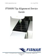
F7000N Tip Alignment Device Guide
Rev. A – May 20
th
2015
Fisnar Inc. | 19C Chapin Rd. Ste. 307, Pine Brook, NJ 07058 | T: (973) 646-5044 | info@fisnar.com |
www.fisnar.com
- Page 11 -
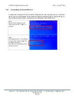
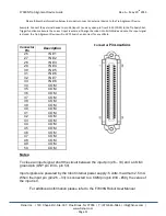
Please follow the information below to properly connect an external device to the Tip Alignment Device.
Example. Connect the external device to pin 26 (Input 1) and any open pin from 34-50 (COM). In the Tip Search Ext.
Trigger function make sure the correct input is entered. Change the robot into RUN Mode and once the input signal
is closed, the Tip Alignment Device will run XYZ Search and correct for any offsets.
Connector
Pin Locations
Notes:
To close an input signal, short the circuit between the input pin (26
– 33) and a COM /
ground pin (ANY pin # 34 - pin 50).
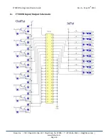
Input signals are powered by the robot internal power supply: 5 volts, maximum 2.5 mA
When the input pin (pin 26
– 33) is connected to a COM pin (pin #34 - #50), the value of
the input is 0.
For additional information please refer to the F7000N Robot User Manual.
Connector
Pin
Description
26
IN # 1
27
IN # 2
28
IN # 3
29
IN # 4
30
IN # 5
31
IN # 6
32
IN # 7
33
IN # 8
34
COM
35
COM
36
COM
37
COM
38
COM
39
COM
40
COM
41
COM
42
COM
43
COM
44
COM
45
COM
46
COM
47
COM
48
COM
49
COM
50
COM

