11
ASSEMBLY INSTRUCTIONS
STEP 6 :
Seat Cushion Installation
1. Remove three ø8xø16x1.5 Flat Washers (37) and three M8 Nylon Nuts (42) from underside
of the Seat Cushion (27). Guide bolts on underside of the Seat Cushion (27) through holes
on top of the Seat Slider (65), attach with three removed Φ8xΦ16x1.5 Flat Washers (37) and
three M8 Nylon Nuts (42). Tighten nuts with Multi Hex Tool with Phillips Screwdriver provided.
2. Attach the Seat Slider (65) onto the Seat Post (25) with one ø10xø25x2.0 Flat Washers (37)
and one M10 Knob(62) by turning it in a clockwise direction to lock the Seat Slider (65).
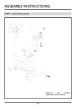
STEP 7 :
Seat Post Installation
1. Insert the Seat Post (25) into the Seat Post Plastic Bushing on the tube of the Main Frame (1)
and then attach the M16 Seat Height Adjustment Knob (8) onto the tube of the Main Frame (1)
by turning it in a clockwise direction to lock the Seat Post (25) in the suitable position.
Adjusting the Seat Back and Forth
Turn the M16 Seat Height Adjustment Knob (8) in a counterclockwise direction to release the
Seat Slider (65) and then slide the Seat Slider (65) back or forth slightly to the desired hole for
the suitable position.Lock the Seat Slider (65) in place by tightening M16 Seat Height Adjustment
Knob (8) in a clockwise direction.
Adjusting the Seat Height
Turn the M16 Seat Height Adjustment Knob (8) in a counterclockwise direction to release the
Seat Post (25) and then slide the Seat Post (25) up or down slightly to the desired hole for the
suitable position. Lock the Seat Post (25) in place by tightening the M16 Seat Height Adjustment
Knob (8) in a clockwise direction.
NOTE: When adjusting the height of seat post, make sure the seat post plastic bushing does not
exceed the mark line on the seat post.
Summary of Contents for F4H-EB-KPR65910
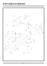
Page 4: ...4 EXPLODED DIAGRAM...
Page 10: ...10 ASSEMBLY INSTRUCTIONS STEP 5 Computer Installation...
Page 12: ...12 ASSEMBLY INSTRUCTIONS STEP 7 Seat Post Installation...
Page 19: ...19...


