9
ASSEMBLY INSTRUCTIONS
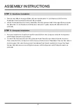
STEP 4 :
Handlebar Installation
1. Remove two M8x15 Hexagon Bolts (24) and two ø8xø16x1.5 Arc Washers (32) from the
Handlebar Post (3) with Allen Wrench S6 provided.
2. Attach the Handlebar (2) onto the Handlebar Post (3) with two M8x15 Hexagon Bolts (24) and
two ø8xø16x1.5 Arc Washers (32) that were removed. Tighten bolts with Allen Wrench S6
provided.
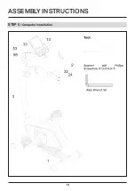
STEP 5 :
Computer Installation
1. Remove two M5x10 Cross Pan Head Screws (33) from the Computer (10) with the Spanner
with Phillips Screwdriver provided.
2. Connect the Extension Sensor Wire (59) and Hand Pulse Sensor Wires (53) with the wires
that comes from the Computer (10).Tuck wires into the hole of Handlebar Post (3), then attach
the Computer (10) onto the top end of Handlebar Post (3) with two M5x10 Cross Pan Head
Screws (33) that were removed.Tighten screws with the Spanner with Phillips Screwdriver
provided.
Summary of Contents for F4H-EB-KPR65910
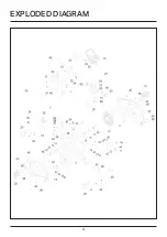
Page 4: ...4 EXPLODED DIAGRAM...
Page 10: ...10 ASSEMBLY INSTRUCTIONS STEP 5 Computer Installation...
Page 12: ...12 ASSEMBLY INSTRUCTIONS STEP 7 Seat Post Installation...
Page 19: ...19...


