56
1
2
5
6
3
4
8
6
9
4
7
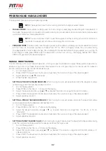
ASSEMBLY
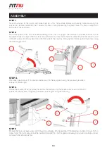
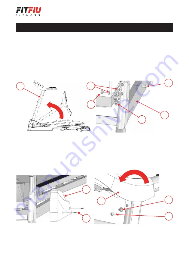
STEP 1.
Take all parts out of the carton and place them on a firm, flat surface. Remove all packing materials. Using the
screwdriver, remove (rotate left) the 2 screws (8, shown in step 3) securing the plastic cover (7, shown in step 3) on
each side of the equipment.
STEP 2.
With the equipment flat, lift the handle assembly (2) so that it is upright, then secure the handle columns to the
equipment base (1) using 2 M8x45 screws (3), washers (4) and nuts (5) on the outer sides of the handle columns, and
4 M8x20 screws (6) and washers (4) on the front side of the columns. Firmly tighten (rotate right) all fasteners using
the Allen key/spanner.
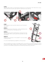
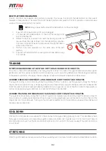
STEP 3.
Place each plastic cover (7) in position and secure it to the equipment using the previously removed
screws (8) (rotate right).
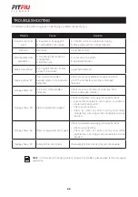
STEP 4.
Rotate the console (9) so it is almost horizontal, then secure it to the handle columns using 2 M8x20
screws (6) and washers (4). Tighten the screws (rotate right) using the Allen key.
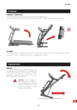
STEP 5.
Prepare the lower accessory bar rail (10) by sliding 2 pieces of tube padding (11), followed by a tube joint cover (12) on
to each end. The joint covers should be inserted small end first. For the upper accessory bar rail, slide a tube joint cover
onto each end, small ends first.

