6
HORIZONTAL WINDLASS MANUAL
VOLUME ONE
1.
Use drilling template provided and choose an appropriate position with reference to
the vessel’s bow roller and the chain locker below. Allow for the rotation of the manual
operating wrench handle
2.
If the deck is not flat, a suitable mounting pad may be required to take up camber or
sheer.
NOTE
: If in doubt about the suitable construction of the pad consult a qualified marine
engineer.
The deck is an integral component of the windlass it has to secure the windlass and be
strong enough to cope with the high torque stresses involved in recovering the anchor.
Decks that are thin, or of foam or balsa laminate construction, will require reinforcement
in order to spread the loads that will be applied to the deck while the windlass is in use.
3. Five Oceans recommends a minimum deck thickness of 25mm (1"), M8 Studs suit deck
and packing thickness of 25-60mm (1" - 2 1/4").
4.5 Below Deck Preparation
4.5 Below Deck Preparation
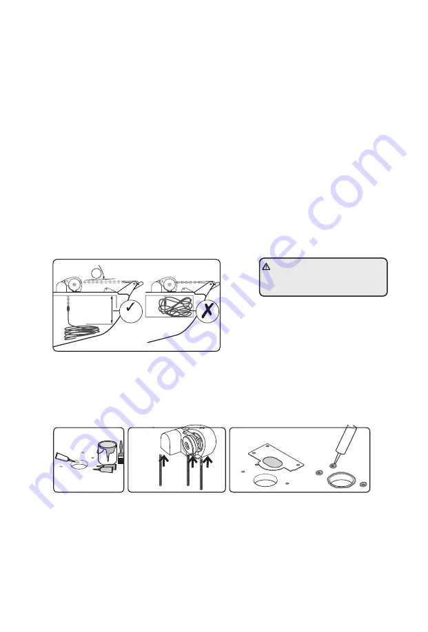
IMPORTANT: The positioning of the windlass must be checked prior to cutting for deck/hull and
bulkhead clearance. Lead from the roller should be fed horizontally back to the top of the gypsy
and along its centre line 6˚. There must be sufficient vertical fall (minimum
of 300 mm /12” at all times) for the chain or rope when hauling in.
4.6 Above Deck Fitting
4.6 Above Deck Fitting
Using the template and after you have checked all the above and below deck requirements cut
the following holes: Using a 10mm (3/ three holes for the mounting studs and two for the 8”)
diameter drill bit, make the motor cables. With a 76mm (3”) diameter hole saw, make one hole
for the rode to pass through.
1.
When all the holes have been made, remove the template. To help avoid water absorption
by the deck, apply an appropriate marine sealant to the freshly cut hole edges.
2.
Assemble and tighten studs into base until they bottom out in their holes.
3. Place the base mat in position on the deck. Apply a suitable sealant to the base of the
windlass, any mounting pad or around the studs.
300 mm
(12”)
6°
1
2
3
WARNING! Failure to respect the
300 mm vertical fall may cause
malfunction.


