background image

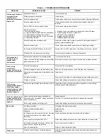
Table 3 — TROUBLESHOOTING GUIDE 

PROBLEM 

PROBABLE CAUSE 

REMEDY 


System fan is not on. 

Turn system fan on. 


Wiring improperly connected. 

Check wiring. 


Defective power switch. 

Check power switch for continuity with multimeter. Replace if defective. 


Defective safety interlock. 

Check interlock switch for continuity with multimeter. Replace if 
defective.


Power (120 V) is not provided to device. 

Check power wiring with multimeter. 


Short in cells due to: 
1.  Broken ionizing wire(s). 
2.  Large particles wedged between cell plate(s). 
3.  Cells washed recently and are still wet. 
4.  Round end plate insulator is burnt or melted. 
5.  Cell plate(s) are bent. 

 
1.  Remove wire or wire fragments, spring and S-hook. Replace. 
2.  Shake large particles out or wash cell. 
3.  Allow cells to dry completely. 
4.  Replace end plate insulator. 
5.  Straighten plates with pliers. 


Defective performance indicator light. 

Determine whether high voltage is present by testing power board. If 
present, replace indicator light. 


Defective power board. 

Check components ahead of power board. Adjust high voltage 


Air Proving Switch (APS) sensor is burnt out. 

Jumper 3 & 4 on APS, close door. If light does not come on, replace 


Off board 24 V transformer is not working. 

Verify output of transformer. Replace if necessary. 


Internal cell contacts are not touching plates. 

Test contacts and repair. 


Copper contacts on high voltage tray not making 
good connection on cell. 

With needle-nose pliers, gently pull contacts up or replace contacts. 


Cells wet from washing. 

Allow cells to dry completely. 


Particle(s) lodged in cell or broken ionizing wire.  Wash cell. Shake particle out of cell. Replace wire, if necessary. 


Ducts were not cleaned prior to installation of air 
cleaner. 

Clean ducts. 


Cell plate(s) are bent. 

Remove cells and adjust to original spacing using needle-nose pliers. 


Voltage is too high. 

Adjust high voltage potentiometer on power board clockwise. 


Contacts on high voltage tray are broken or bent.  If possible, pull up contacts with needle-nose pliers or remove high 

voltage tray and replace contacts. 


Arrow on cell(s) not pointing towards back. 

Reposition cells. 


System fan is on “Automatic” setting (air cleaner 
not on continuously) 

Use “Fan On” system fan setting for continuous fan operation. 


Not enough voltage on collecting cells. 

Adjust high voltage potentiometer clockwise on power board. 

Ozone odor 

Cell plate(s) are bent. 

Straighten with needle-nose pliers. 


Loose or broken ionizing wire(s). 

Replace wires. 


Dirty cells. 

Wash cells. 


Air Cleaner is on when system fan is not running. 
Air switch not activated or air cleaner wired 
incorrectly. 

Check operation and wiring of air switch and air cleaner. 


Incoming voltage is higher than 120 V. 

Adjust high voltage potentiometer counter-clockwise on power board. 


Air Cleaner is oversized for house. Not enough 
airflow to cover surface area of cells. 

Use correct size of Air Cleaner. 


Home is extremely dry. 

Repair or install central humidifier. 


Clean lint dust too heavy to remain airborne. 

Keep fan running continuously. Ensure that return air grilles are not 
obstructed. 

Unit does not function 
correctly. Power 
switch on and 
performance indicator 
light is off. 

Cell makes loud 
hissing noise or 
causes radio 
interference. 

Cells arcing 
excessively 
(power switch on and 
performance indicator 

Cells not collecting dirt 
(power switch on and 
performance indicator 
light on). 

White dust 

Cells arcing 
excessively at bottom 
of cell near copper 
contacts (power switch 
on and performance 
indicator light on). 

Summary of Contents for FS-GM20AS-A

Page 1: ...cting Cells are durable and easy to maintain Plastic Intake Grille is easy to wipe clean Hinged Swing Out Door allows easy access to filters Automatic interlock switch disconnects power when unit is opened Durable Scratch Resistant powder coat paint finish resists abrasion Electronic Air Proving Switch allows for quick wiring and cycles air cleaner on off with system fan Indicator Light shows Air ...

Page 2: ...mospheric and household dust coal dust insecticide dust mites pollen mold spores fungi bacteria pet dander cooking smoke and grease tobacco smoke particles and more down to 0 01 micron 0 01 micron 1 2 540 000 of an inch BENEFITS Helps provide relief for allergy or asthma suffering Helps prevent damaging black dust from staining walls and furnishings reducing the amount of time and money spent clea...

Page 3: ... the enclosure Remove the five screws securing the electrical compartment cover The hole in wall or ceiling should be made to fit the Air Cleaner opening as closely as possible The opening should be framed to provide adequate support for the Air Cleaner Before mounting the Air Cleaner cover the framing and close the opening to within 1 4 in 63 cm of the dimension of the rear of the enclosure of th...

Page 4: ...etergent is available from your installer or dealer SERVICE Testing Air Proving Switch APS The APS sensor must protrude into the airstream to work effectively The sensor is very sensitive and operation may be affected by cold temperatures an air exchanger or a fresh air duct connected to the cold air return near the Air Cleaner The APS uses a Triac in its output circuit which affects the voltage s...

Page 5: ...urn off power to the Air Cleaner at the source 1 Remove the electrical compartment cover 2 Disconnect wiring from the LED HV1 HV2 and 24 V terminals 3 Remove the hex nut from the power board 4 Release the power board from the 3 plastic board spacers by pinching the end of the spacers and pulling the board out 5 Push new board onto spacers Make sure spacers click into place to hold down board 6 Scr...

Page 6: ...age should be reset with a high voltage meter as soon as possible 1 Remove electrical compartment cover 2 Turn the HV ADJ potentiometer fully counterclockwise Air Cleaner may arc or snap at this point 3 Turn the HV ADJ potentiometer clockwise slowly until the arcing and snapping stops 4 Replace electrical compartment cover Testing Cell For Bad Contact 1 Turn off power switch Open access door to Ai...

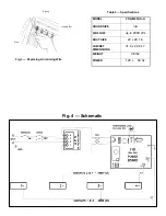
Page 7: ...nizing Wire Table 2 Specifications Ionizing Bar Spring Wire Fig 4 Schematic MODEL FS GM20AS A HOUSE SIZE n a AIR FLOW up to 2000 cfm DUCT SIZE 22 x 29 1 in CABINET DIMENSIONS 31 4 x 24 4 x 7 WEIGHT 38 lbs POWER 120 v 60 hz ...

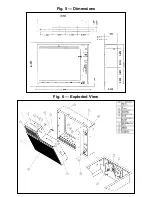
Page 8: ...Fig 6 Exploded View Fig 5 Dimensions ...

Page 9: ...ry Ducts were not cleaned prior to installation of air cleaner Clean ducts Cell plate s are bent Remove cells and adjust to original spacing using needle nose pliers Voltage is too high Adjust high voltage potentiometer on power board clockwise Contacts on high voltage tray are broken or bent If possible pull up contacts with needle nose pliers or remove high voltage tray and replace contacts Arro...

Page 10: ...arts or replacement parts Such costs may be covered by a separate warranty provided by the dealer LIMITATIONS OF WARRANTY All implied warranties including implied warranties of merchantability are hereby limited in duration to the period for which the limited warranty is given The expressed warranties made in this warranty are exclusive and may not be altered enlarged or changed by any distributor...

Reviews: